Service and Repair Manual April 2017
Manifolds
60 GS-30 • GS-32 • GS-46 • GS-47 Part No. 1272217
5-3
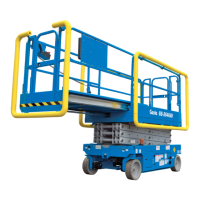
Function Manifold Components – GS-4047
The function manifold is mounted behind an inspection door, at the ground control side of the machine.
Index No. Description Schematic Item Function Torque
— Coil nut (item DC) — — 4-5 ft-lbs / 5-7 Nm
— Coil nut (items DE, DG and DI) — — 5-7 ft-lbs / 7-9 Nm
1 Diagnostic port DA Test port —
2
Relief valve, 3500 psi / 241 bar
maximum
DB System relief 20 ft-lbs / 27 Nm
3 Solenoid valve, 3 position 4 way DC Steer left/right 25 ft-lbs / 34 Nm
4 Check disc DD Steer circuit 18 ft-lbs / 24 Nm
5 Solenoid valve, 2 position 4 way DE Drive speed select
circuit
25 ft-lbs / 34 Nm
6 Relief valve, 50 psi / 3.4 bar DF Brake release 20 ft-lbs / 27 Nm
7 Solenoid valve, 3 position 5 way DG
Drive
forward/reverse
25 ft-lbs / 34 Nm
8 Flow regulator and relief valve,
0.75 gpm / 2.8 L/min,
1500 psi / 103 bar
DH Steer circuit 26 ft-lbs / 35 Nm
9 Solenoid valve, 2 position 4 way DI Platform up 25 ft-lbs / 34 Nm
10 Relief valve, 3000 psi / 207 bar DJ Lift relief 20 ft-lbs / 27 Nm
How to Install a Valve Cartridge
1 Dip the cartridge in clean oil to lube the O-rings.
2 Screw the cartridge in by hand until the top O-ring is met, then torque to specifications.
3 If required, install the valve coil(s) onto the valve stem. Install the coil nut onto the valve stem and
torque to specifications.
 Loading...