12
Installation
Attention
LRGT 16-1, LRGT 17-1
Provide spacing of approx. 30 mm between the lower end of the measuring tube and
the boiler wall, the smoke tubes and any other metallic fittings, and the low water level
(LW).
Do not cut the measuring electrode or measuring tube!
LRGT 16-2
Provide spacing of approx. 60 mm between the lower end of the measuring tube and
the boiler wall, the smoke tubes and any other metallic fittings, and the low water level
(LW).
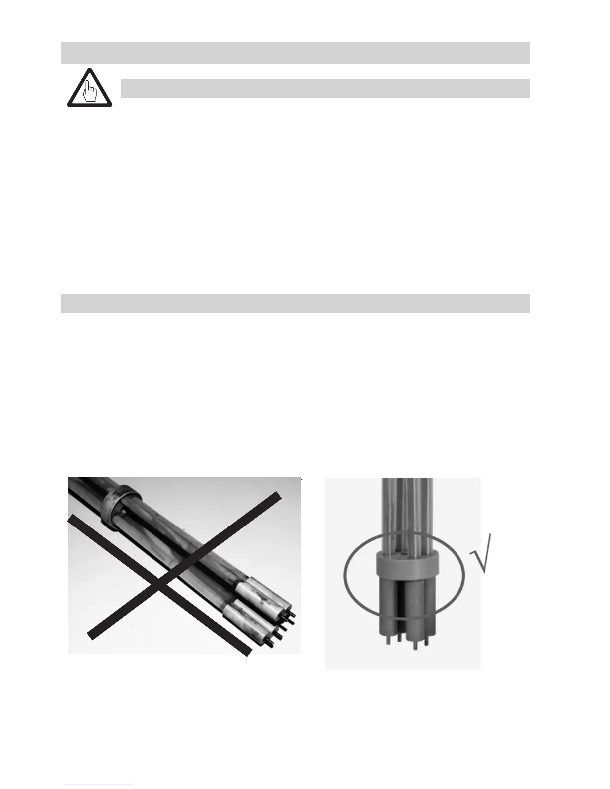
Do not cut the measuring electrodes!
Do not subject measuring electrodes to physical shocks!
Do not bend electrode rods when mounting!
Mounting the conductivity transmitter
1. Check seating surfaces. Fig. 4
2. Place the supplied sealing ring 3 onto the seating surface of the threaded coupling or flange.
3. Apply a light smear of heat-resistant silicone grease (e.g. WINIX
®
2150) to the electrode thread 5.
4. Screw the conductivity transmitter into the threaded coupling or flange and tighten with an open-
end spanner 41 mm A.F. The torque required for tightening when cold is 240 Nm.
Additionally for LRGT 16-2
5. Distribute the spacer discs 7 evenly (length 800 mm onwards).
6. Check that the lower spacer disc PEEK 8 is correctly seated. Fig. 5
Fig. 5
 Loading...


