9
Scope of supply
LRGT 16-1
1 Conductivity transmitter LRGT 16-1
1 Sealing ring 33 x 39, form D, DIN 7603, 1.4301, bright annealed
1 Installation & Operating Instructions
LRGT 16-2
1 Conductivity transmitter LRGT 16-2
1 Sealing ring 33 x 39, form D, DIN 7603, 1.4301, bright annealed
1 Installation & Operating Instructions
LRGT 17-1
1 Conductivity transmitter LRGT 17-1
1 Sealing ring 33 x 39, form D, DIN 7603, 1.4301, bright annealed
1 Installation & Operating Instructions
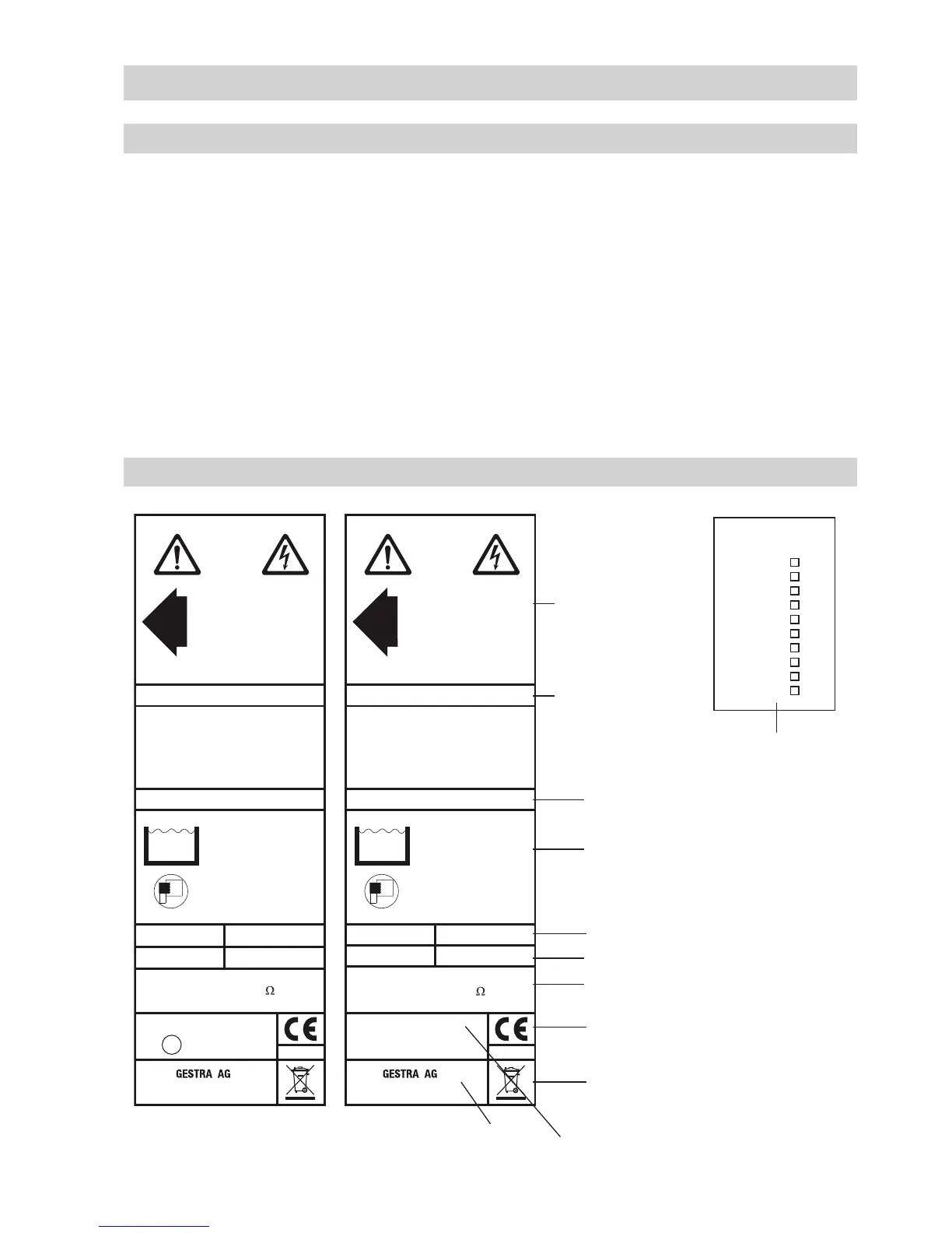
Technical data
Equipment
designation
Pressure rating, thread type,
material number
Information on area of application
Key electrical data
Measuring range
Actual value output data
CE marking
Manufacturer
Safety note
Disposal note
Name plate/marking
33254-06-HH
GL
0525
24 V DC
Pmax
Tmax
LRGT 16-1
0,5-12000µS/cm
OUT:4-20 mA / 750
4,5 W
0,25-6000ppm
Leitfähigkeitstransmitter
Conductivity Transmitter
Transmetteur de mesure
de conductibilité
Münchener Str.77
D-28215 Bremen
Betriebsanleitung
beachten
See installation instructions
Voir instructions de
montage
Tamb = 70°C (158 °F)
PN40 G1 1.4571 IP65
32 bar (464psi)
238°C (460°F)
TÜV . WÜL . xx-003/xx-017
0525
24 V DC
Pmax
Tmax
LRGT 16-2
100-10000µS/cm
OUT: 4-20 mA / 750
4,5 W
50-5000ppm
Leitfähigkeitstransmitter
Conductivity Transmitter
Transmetteur de mesure
de conductibilité
Münchener Str. 77
D-28215 Bremen
Betriebsanleitung
beachten
See installation instructions
Voir instructions de
montage
Tamb = 70°C (158 °F)
PN40 G1 1.4571 IP65
32 bar (464psi)
238°C (460°F)
TÜV .WÜL . xx-003
TÜV .WÜL . xx-017
33254-06-HH
GL
0525
24 V DC
Pmax
Tmax
LRGT 16-1
0,5-12000µS/cm
OUT:4-20 mA / 750
4,5 W
0,25-6000ppm
Leitfähigkeitstransmitter
Conductivity Transmitter
Transmetteur de mesure
de conductibilité
Münchener Str.77
D-28215 Bremen
Betriebsanleitung
beachten
See installation instructions
Voir instructions de
montage
Tamb = 70°C (158 °F)
PN40 G1 1.4571 IP65
32 bar (464psi)
238°C (460°F)
TÜV . WÜL . xx-003/xx-017
 Loading...


