16
Electrical connection
To connect the conductivity transmitter, please use a screened, multi-core control cable with a min.
conductor size of 0.5 mm
2
, e.g. LiYCY 4 x 0.5 mm
2
, max. length: 100 m.
Route connecting cables leading to the equipment separate from power cables.
1. Slacken the screws f and remove the housing cover g. The arrow on this cover points to the name
plate. Fig. 1, 9
2. Detach the terminal strip n from the circuit board.
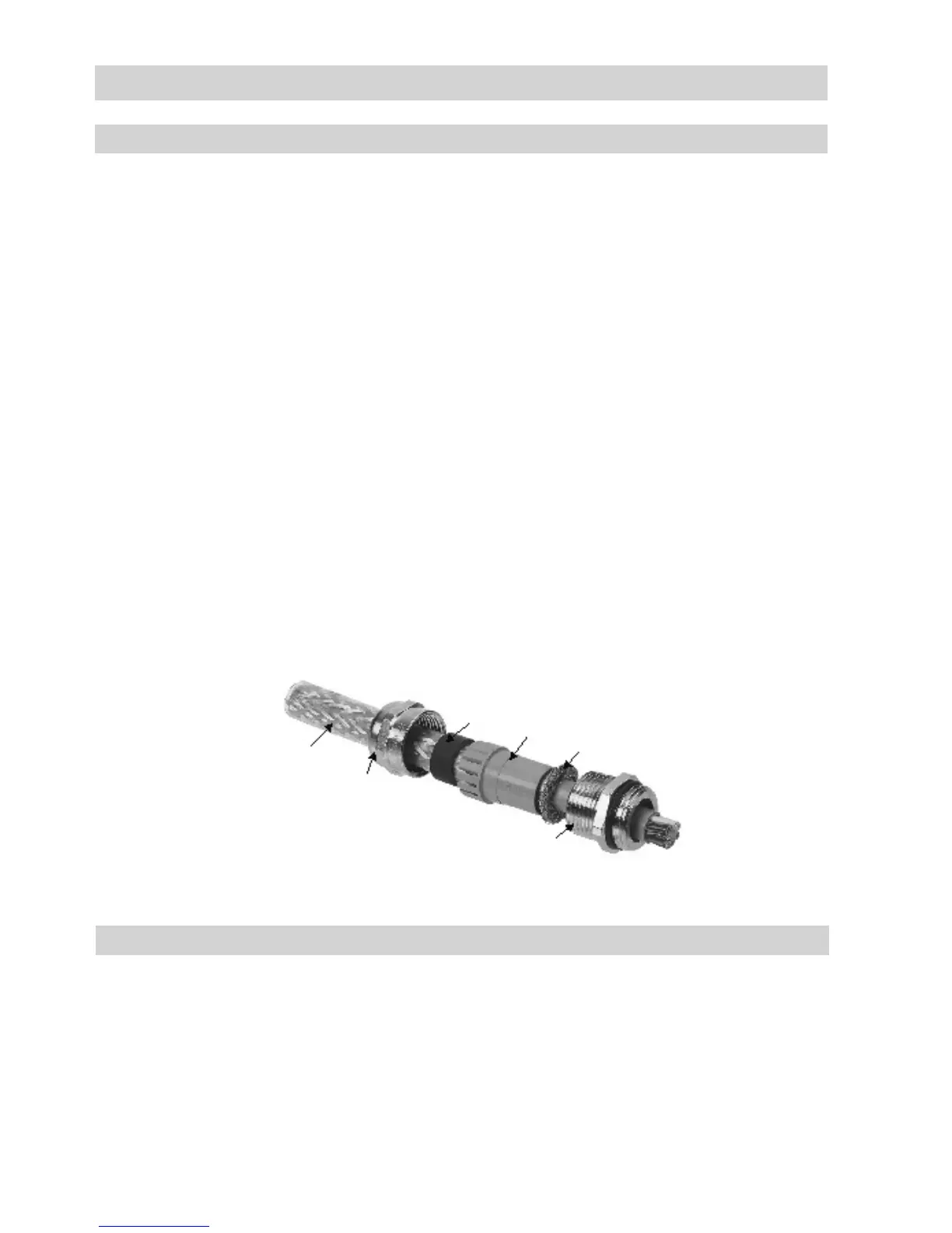
3. Unscrew the cap nut u of the cable gland h and remove the lamellar insert s.
Fig. 11
4. Strip the outer sheath of cable v and expose the braided screen r over a length of
approx. 10 – 15 mm.
5. Push the cap nut u and lamellar insert s with the sealing ring t onto the cable.
6. Bend braided screen r outwards at right angles (90°).
7. Fold the braided screen r towards the outer sheath, i.e. by 180° in total.
8. Push the lamellar insert s with sealing ring t into the gland body q, turn briefly to and fro around
the cable axis and snap anti-rotation element into place.
9. Firmly screw on the cap nut u.
10. Connect the individual cables to the terminal strip n as shown in the wiring diagram.
11. Re-attach the terminal strip n to the circuit board.
12. Replace the cover g and fasten the cover screws f.
Connecting LRGT 16-1, LRGT 16-2, LRGT 17-1
continued
Fig. 11
t
r
q
v
u
s
Key
j Code switch
m Terminal lugs for electrode wires,
functional earth
n Terminal strip
p Connection for functional earth
q Gland body
r Braided screen
s Lamellar insert
t Sealing ring
u Cap nut
v Screened cable
 Loading...


