21
If there is a deviation between the indicated conductivity and the measured comparison value,
check and change the temperature coefficient T
k
setting. See page 20 for procedure and setting
values.
Only modify the cell constant if the temperature coefficient setting is no longer sufficient for
correct compensation.
Correcting the measured value
Operation
Adjusting the cell constant
The factory-set cell constant is a geometric characteristic of the equipment used for calculating
conductivity. However, this constant may change over time, e.g. due to dirt deposits.
Depending on the deviation, set code switch 8 or 9 briefly to ON and then to OFF again.
Repeat this step until the indicated value matches the measured comparison value.
If the conductivity transmitter and conductivity controller are physically separated from one another,
measure the current at the transmitter or have a second person perform the adjustment.
If adjustment is no longer possible, remove the transmitter and clean the measuring surface and/or
electrodes.
Note
Repeat the cell constant adjustment procedure until the indicated conductivity matches
the measured comparison value. The cell constant can be reset to its default value. To
do so, set code switches 8 and 9 simultaneously to ON then back to OFF after approx. 1
second.
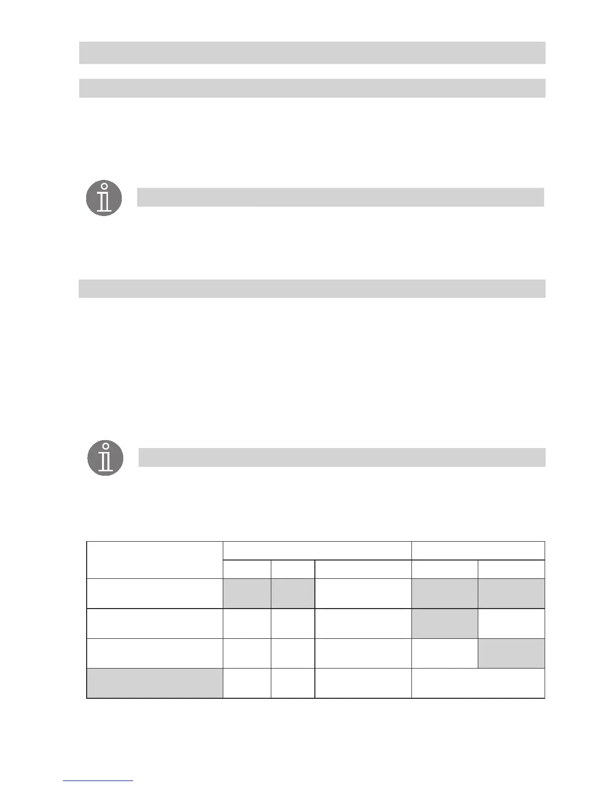
Deviation in indicated con-
ductivity
Code switch LED indicator
8 9 Function green red
None OFF OFF No change
Indicated value below
measured comparison value
ON OFF Cell constant increases flashing rapidly
Indicated value above
measured comparison value
OFF ON Cell constant decreases flashing rapidly
ON ON
Restores
default factory setting
both flashing rapidly
Note
For the procedures of modifying the cell constant, performing a function test and
observing the LEDs, open the terminal box by slackening the screws f and removing
the housing cover g. The arrow on this cover points to the name plate. Fig. 1, 9
 Loading...


