22
Operation
Function test
1. To check the functions of the conductivity transmitter, set code switch 10 to ON. This simulates a
value that exceeds the measuring range limit and provides a current output of 20 mA.
2. After finishing the function test, set the code switch back to OFF.
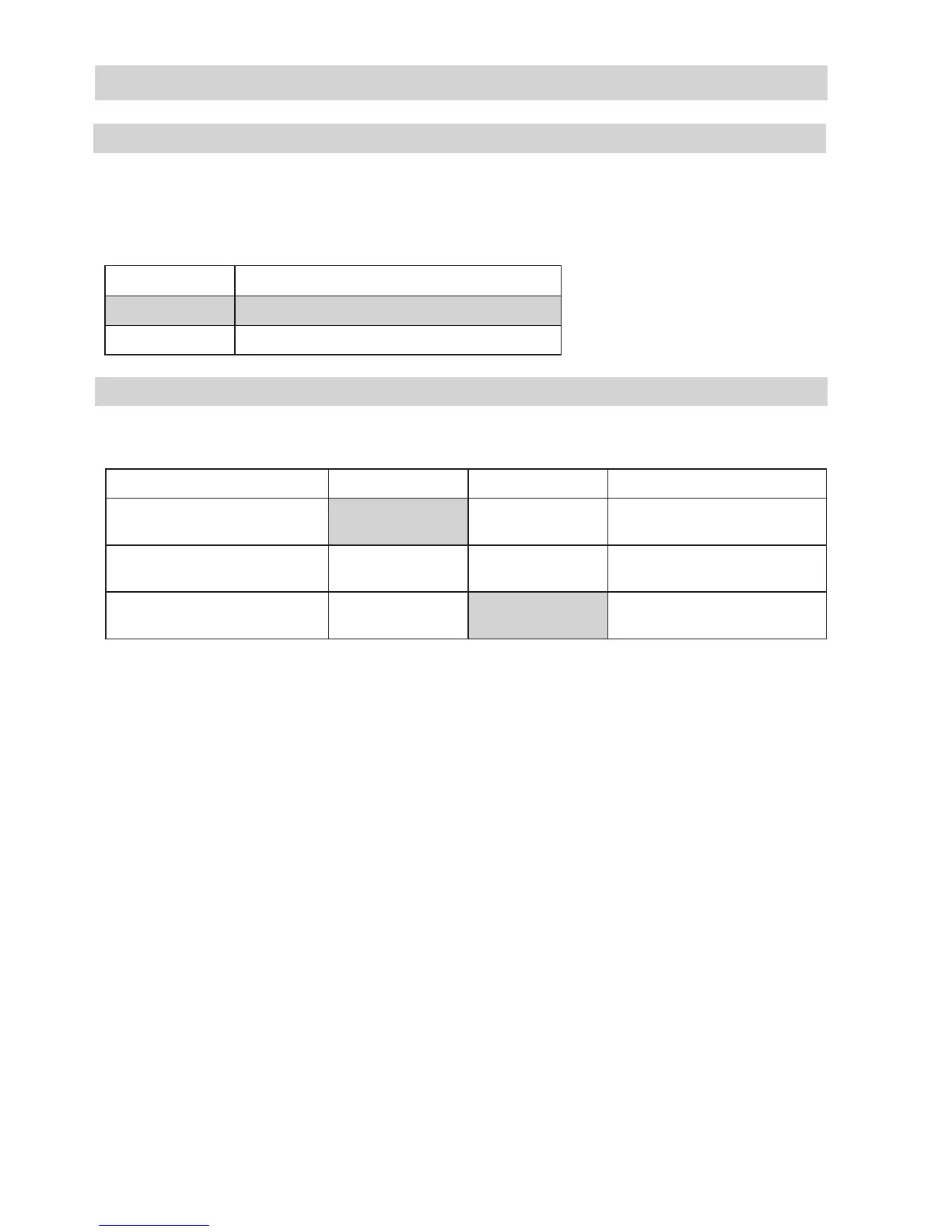
Code switch 10 Function test
OFF Normal operation
ON Simulation: measuring range limit exceeded
The two LEDs in the middle of the electronic circuit board indicate the status of
the conductivity transmitter.
Normal operation Green LED Red LED Current output [mA]
Conductivity 0 to + 10 %
of measuring range
lit up proportional to measured value
Conductivity 10 to + 90 %
of measuring range
lit up lit up proportional to measured value
Conductivity 90 to + 100 %
of measuring range
lit up proportional to measured value
LED indicator
continued
 Loading...


