R*
Installation examples
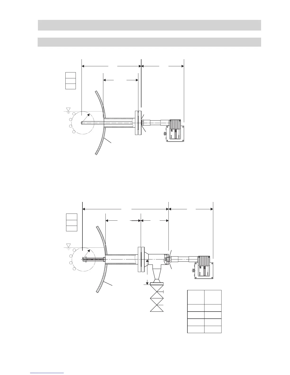
LRGT 16-1, LRGT 16-2, LRGT 17-1
Fig. 6
Conductivity monitoring, conductivity transmitter directly installed via flanged connection on side of boiler
LRGT 16-1
LRGT 16-2
LRGT 17-1
0
a
415
336
G 1 A, ISO 228
R*: LRGT 16-1, LRGT 17-1 R = 30 mm
LRGT 16-2 R = 60 mm
Conductivity monitoring and continuous boiler blowdown, direct installation of conductivity trans-
mitter via T-type connector and connection of a continuous blowdown valve
Fig. 7
LRGT 16-1
LRGT 16-2
LRGT 17-1
R*: LRGT 16-1, LRGT 17-1 R = 30 mm
LRGT 16-2 R = 60 mm
~ 250
NW
LW
NB
R*
GESTRA
Steam Sy
stems
GESTRA
Steam Sy
stems
GE
STR
A
LRGT .
...
GE
STR
A
LRGT
µS-ppm
600 336
~ 250 197
G 1 A, ISO 228
DN
A
[mm]
15 182
20 184
25 184
40 189
0
d
c
b
a
DN 50
DN 50
A
 Loading...


