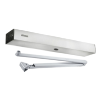
ECturn Inside
20
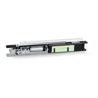
Installation
Electrical connection
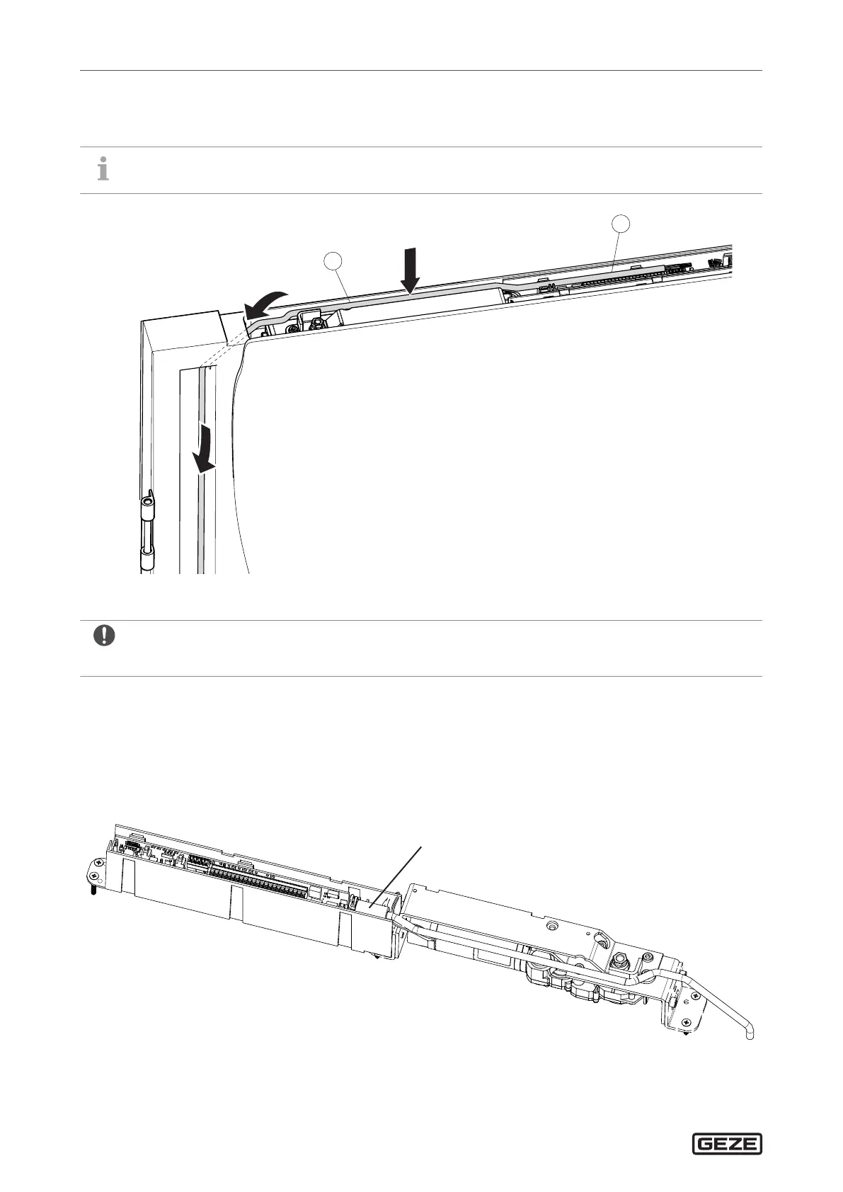
X
Push the 6-wire cable (1) (2x 1mm² for 24V / 4x 0.25mm² for electric strike, contact sensor etc.) into the pre-
pared door passage from above and through the drip loop.
In the case of metal doors, this cable is already inserted when the door is built.
Route cable (1) along the motor gear unit (arrow) to the control circuit board (2).
X
Do not shorten the cable (1) too much.
Leave the length of the wire cores that are not required so that all the terminals of the control circuit board can
be reached if necessary later.
X
Strip the insulation from both 24 V wire cores (red, blue) and fit with insulating 1mm² wire end ferrules
Push the wire end ferrules through ferrite ring cores and connect to the plug
X
Insert the plug into the control circuit board.
Ferrite ring core