Instruction manual Mounting the Multifunctional Module in the Ball Valve
7
3 Mounting the Multifunctional Module in the Ball Valve
Immediately prior to installation, inspect the MF module for transport damages. We
recommend leaving the MF module in its original packaging until you are ready to install it.
The MF module has been fitted ex works with the respective switches and function-tested! It
is not necessary to remove the cover when used with the hand-operated ball valve.
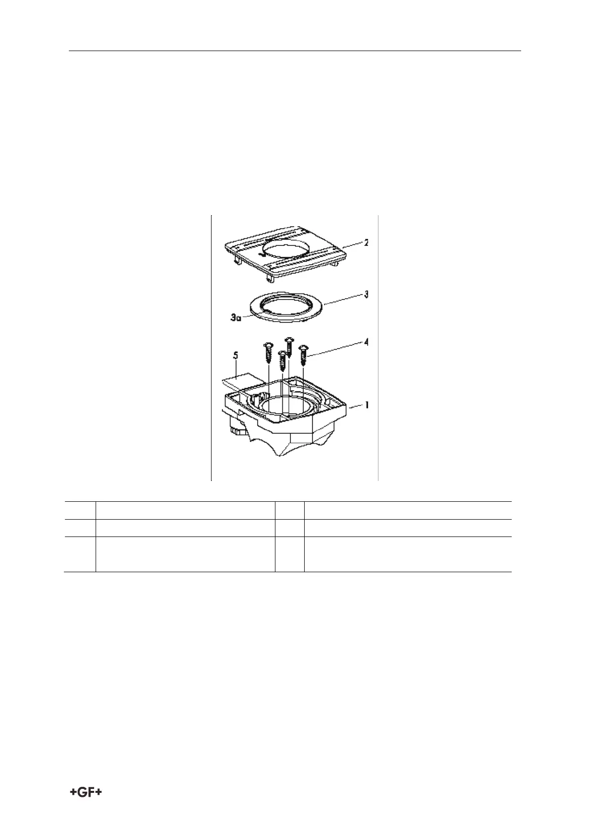
Design of the MF module with built in switches
1
Housing
3a
Switching cam
2
Housing cover
4
Stainless steel Torx screws
3
Switching disc*
5
Connector plug 3P + E per DIN
EN ¢75301-803 (formerly DIN 43650)
*) for MF module versions with pre-assembled Micro Switches
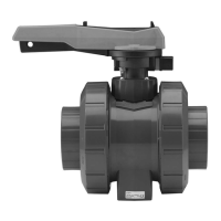
The MF module can be mounted on the ball valve type 546 in the opened or closed ball
position.
ATTENTION! The stem is asymmetrical.
The stem position must be identical to one of the two illustrations.