46
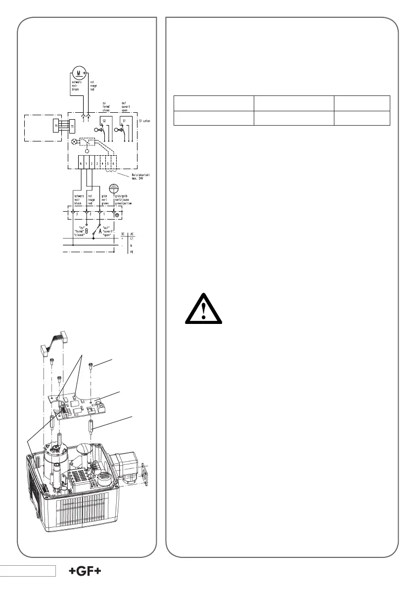
Wiring diagram
Heating element kit
7. Mounting and Connecting
Supplementary Kits
7.1 Heating Element
Description Technical data Code
Heating element 24 V= 199 190 086
The heating element is mounted on the base board and is
connected electrically via a at cable (X1). The temperature
is measured with a temperature sensor, which is mounted
on this element, and between approx. 0 - 5°C the heating
element is switched on.
Mounting the heating element (board)
1. Disconnect the actuator from the supply voltage.
2. Remove actuator cover.
3. Take the board out of its packaging and check for damages.
Do not touch the board itself. Electrostatic
discharge can damage the components.
4. Screw the three distance bolts (1) into the assembly
bolts. Screw hand-tight.
5. Fasten the board (3) on the distance bolts with the sup-
plied screws (2).
6. Plug the at cable into the X1 (4) connector.
7. Put the cover back onto the actuator.
8. Reconnect to supply voltage.
The heating element may not heat at temperatures over
+ 5 °C, but in case it is switched on it might heat up to
10-15 °C.
1
2
3
4
LED on =
heating operation