49
7.3 Additional Limit Switches
Description Technical
data
Code
Kit with 2 additional*
limit switches Ag-Ni
250 V ~, 6 A 199 190 092
Kit with 2 additional*
limit switches Au
30 V =, 100 mA 199 190 093
Kit with 2 additional
limit switches NPN
10-30 V=,
100 mA
199 190 096
Kit with 2 additional
limit switches PNP
10-30 V=,
100 mA
199 190 095
Mounting set for 4 limit
switches
199 190 097
* The switches are wired as openers according to the dia-
gram. It is possible for the customer to convert to closer by
rewiring.
(Terminal 8 > 7 and terminal 10 > 9).
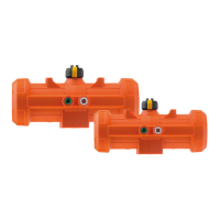
Mounting the limit switches
1. Disconnect the actuator from the supply voltage.
2. Remove the screws from the limit switches S1 and S2.
3. Mount the limit switch kit (1) on S1 and S2 as shown.
4. Tighten with the new, longer screws.
5. Mount the additional switching cams (2) as well as the
spacer rings (3).
Wiring diagram
1
2
3
B)
B)