40
In addition, the operating instructions of the manual valve
must be observed. They are an integral component of this
manual.
4.3 Transport and Storage
The actuators must be handled, transported
and stored with care. Please note the following
points:
• The actuators should be transported and/or stored in
their original unopened packaging.
• The actuators must be protected from harmful physical
inuences such as dust, heat (humidity).
• It is important that the connections are neither dama-
ged by mechanical nor by thermal inuences.
• Prior to installation, the actuators should be inspected
for transport damages. Damaged actuators must not be
installed.
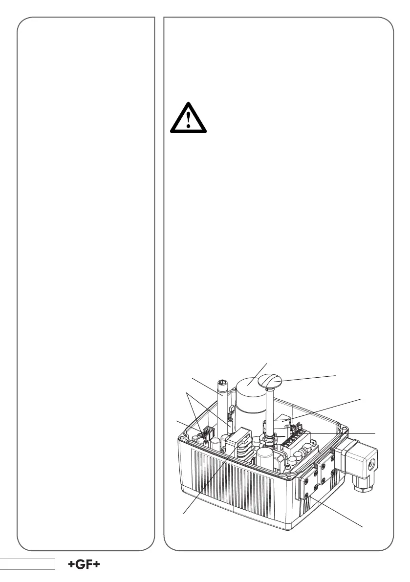
5. Actuator Design
The standard version of the EA 21/31/42 electrical actuator
consists of the following elements: gear unit, direct current
motor, electrical board and components for end position
limiting.
For special applications, the actuator can be equipped addi-
tionally with various supplementary kits (see section 7).
1
2
3
5
6
8
7
1. Limit switches S1 and S2
2. Direct current motor
3. Optical position indicator
4. Plug X1 for accessories
5. Terminal strip for external
connections max. 1.5 mm
2
6. Wide range power supply,
without protection against
accidental contact
7. Shaft for emergency manual
override
8. Connections for DIN plug or
cable gland
9. Assembly bolts for accesso-
ries
4
9