Installation Instruction Manual
30
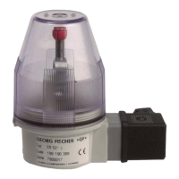
5. Loosen the screw 2 on the electrical position indicator.
6. Unscrew the transparent, protective cover 3.
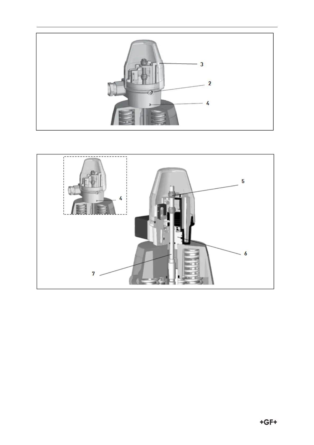
7. Pull upper cam 5 off.
8. Loosen the threaded bolt 4
9. Pull the base 6 with the spindle 7 out of the housing.
10. Screw the base 6 with a wrench into the adapter.
11. Screw the spindle 7 with an Allen key into the spindle nut of the actuator (Attention: left
thread).
12. Place housing on base 6:
- Make sure that the electrical connection is in the desired position.
- Secure threaded bolt 4.
13. Put upper cam 5 on the spindle 7.
14. Do electrical connections according to chapter 7 „Electrical Connections“.