14
PASS
15
PASS
UK UK
EMBEDDING THE PLATE
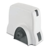
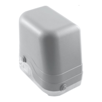
INSTALLING THE GEARMOTOR
FITTING THE RACK
Check that the area where the gearmotor will be fitted is not exposed to flooding. If so, install the gearmotor in a
position raised from the ground;
if the gate is not a new installation, check the state of wear of all the components, repair or replace the defective or
worn parts and perform any other operations necessary.
Use mechanical limits to handle leaf travel excess situations.
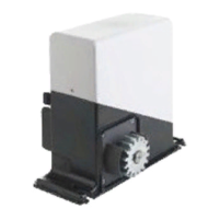
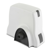
1 – Put the fixing brackets and remove the gearmotor's cover unscrewing the lateral screws [7];
2 – Put the gearmotor on the foundation plate and pass the pins through the suitable slots [8];
3 – Keep the gearmotor 2/4 mm up and lower it after finishing fixing the rack [9a – 9b];
4 – Screw the 4 nuts to fix the gearmotor parallel to the gate [9a – 9b];
1- Manually move the gate to the closed position;
2- unlock the gearmotor (see paragraph Unlocking Device);
3- arrange the rack (optional)[10 - 11 - 12];
4- place the first element of the rack on the pinion in such a way that it protrudes 50 mm from the gearmotor [13]
creating the space required for the limit switch bracket;
5- secure the element in the slot with a screw or spacer depending on the type of rack chosen [10 - 11 - 12]. It is
advisable to tighten the rack retaining screws at the top of the slot so that the gate can be raised and the necessary
clearance between the rack and pinion maintained should the gate lower;
6-continue fitting the rack, aligning the modules one after another; to properly secure the modules, use a piece of
rack of about 150 mm to allow for tooth timing [14]. Once the last module has been secured, cut off the protruding
part with a saw.
7- when all the modules have been fitted, manually carry out various gate opening and closing manoeuvres to check
that it slides smoothly without friction;
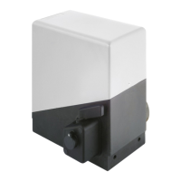
8- lower the operator and lock the gearmotor leaving a clearance of 2 mm between the pinion and the rack [15] to
ensure that the weight of the gate does not negatively affect the gearmotor shaft.
1- Make the hole for the foundation plate respecting the dimensions [2] and arrange the plate according to the closing
direction of the gate [4]. The hole depth must be at least equal to the length of the cramp-irons [5].
2- Fit the flexible hoses through which the electric cables will run so that they lead out of the plate [4] and protrude
from the hole by about 30-40 mm [5].
3- Make sure that the plate is level [5] and start filling the hole with concrete.
4- Wait for the concrete to dry.
5-Run the electric cables (for connection of the accessories and electrical power supply) through the flexible hoses.
To make it easier to make the electrical connections to the control unit, it is advisable to keep a cable length of 400
mm from the foundation plate hole [5].
FITTING THE LIMIT SWITCHES [16]
USING THE DECELERATION FUNCTION
1-insert the nuts u in the hexagonal seats on the magnet holder p;
2- insert the grub screw and nut q in the magnet holder p making sure that it protrudes towards the rack w by at
least 1-1.5 mm;
3- insert the adjusting screw and nut y in the hexagonal seat of the magnet holder p;
4- assemble the bracket e using the screws provided r and insert the grub screws t.
NOTE: at this stage, it is sufficient to assemble the unit to then position it on the rack without having to tighten the
screws.
5- Position the complete limit switches on the rack in the appropriate positions.
NOTE: the limit switch marked on the cover with the letter "O" must be secured in correspondence to the gate-open
position and the one marked "C" in the gate-closed position [19]. To ensure this condition in applications where
the motor is installed on the "left" [19] invert the motor power cables.
Note with reference to Figure [19]
C2: Limit switch “C” Motor off during closing
C1: Limit switch “C” Deceleration start during closing
O2: Limit switch “O” Motor off during opening
O1: Limit switch “O” Deceleration start during opening
6- To fasten the limit switch, first tighten the two screws r, then act on the screw y to adjust the clamp distance
depending on the type of rack and then act on the grub screws t to securely lock the bracket to the rack.
WARNING: Do not overtighten the grub screws t so as not to deform the bracket.
7- Should the limit switch not yet be sufficiently integral with the rack, you can adjust it by unscrewing the screw y.
WARNING: Do not exceed in this adjustment since you may deform the bracket.
If using GI.BI.DI. boards that have the deceleration control function, remember to position 2 pairs of limit switches as
shown [19].
ADJUSTING THE CLUTCH [20]
ATTENTION: Before beginning to adjust the clutch, disconnect the power supply by turning off the main switch.
Insert the size 6 Allen wrench into the socket w .
Remember that turning the wrench clockwise increases the thrust and turning it counterclockwise decreases the
thrust.
If the shaft also rotates when you turn the Allen wrench, line the two sockets q up (the one on the shaft with the
one on the flange). Then insert a screwdriver e and use the Allen wrench to adjust the clutch.
Ÿ
Ÿ
 Loading...