- 23 - Hardware Installation
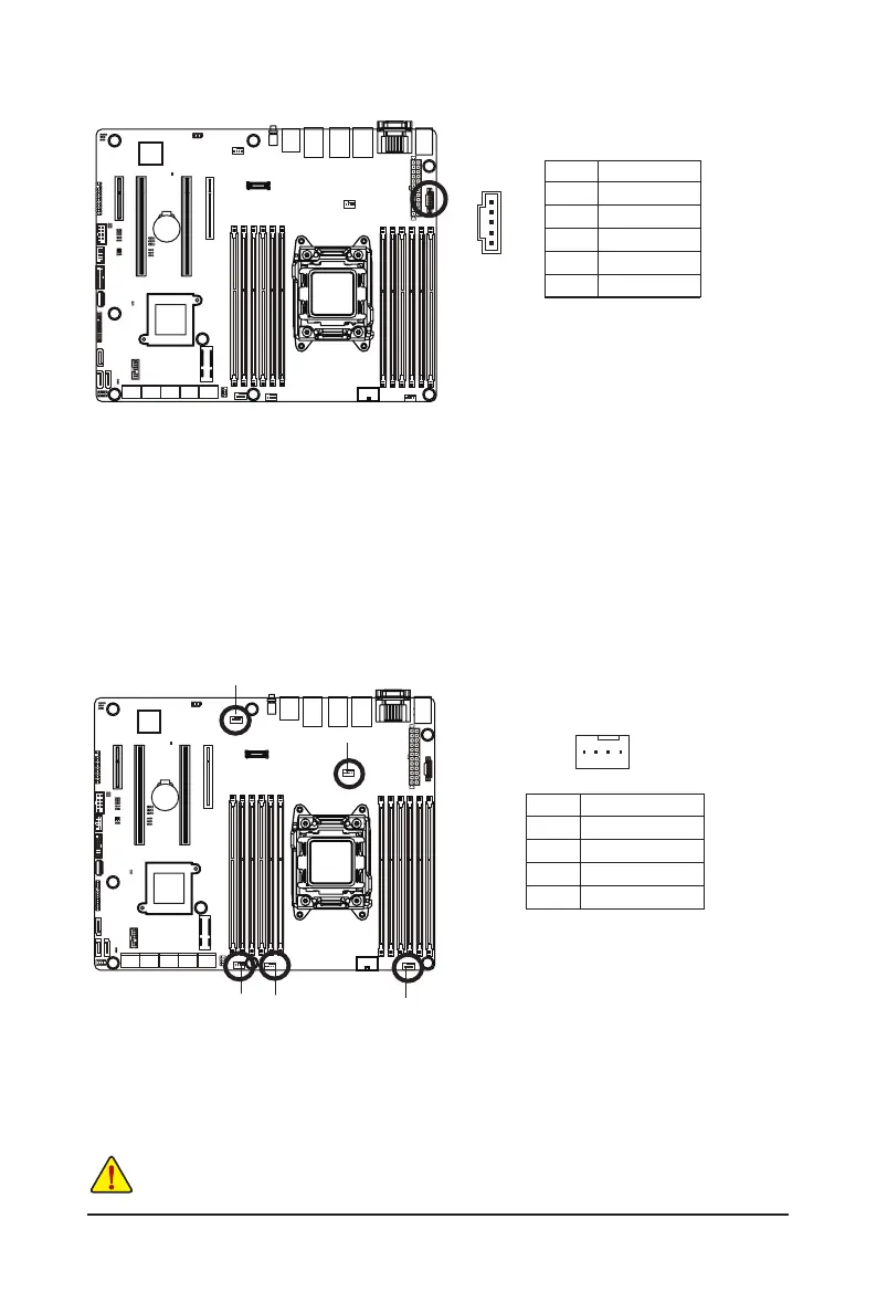
4/5/6/7/8) CPU_FAN/SYS_FAN1/SYS_FAN2/SYS_FAN3/SYS_FAN4
(CPU Fan/System Fan Headers)
The motherboard has one 4-pin CPU fan headers, and four 4-pin system fan headers. Most fan
headers possess a foolproof insertion design. When connecting a fan cable, be sure to connect it in the
correct orientation (the black connector wire is the ground wire). The motherboard supports CPU fan
speed control, which requires the use of a CPU fan with fan speed control design. For optimum heat
dissipation, it is recommended that a system fan be installed inside the chassis.
• Be sure to connect fan cables to the fan headers to prevent your CPU and system from
overheating. Overheating may result in damage to the CPU or the system may hang.
• Thesefanheadersarenotcongurationjumperblocks.Donotplaceajumpercapontheheaders.
PinNo. Denition
1 GND
2 +12V
3 Sense
4 Speed Control
1
CPU_FAN
3) PMBUS (PMBus connector)
1
5
PinNo. Denition
1 PMBus CLK
2 PMBus DATA
3 PMBus Alert
4 GND
5 3.3V Sense
SYS_FAN1
SYS_FAN2SYS_FAN3
SYS_FAN4
 Loading...