- 7 -
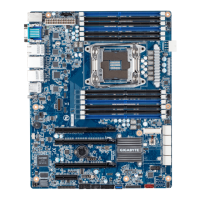
Item Code Description
1 IPMB IPMB connector
2 SYS_FAN4 System fan connector#4
3 SW_ID ID switch button
4 MLAN BMC Management LAN port
5 USB3_LAN1 LAN1 port (top) / USB 3.0 ports (bottom)
6 USB3_LAN2 LAN2 port (top) / USB 3.0 ports (bottom)
7 LAN_3_4 LAN ports
8 COM1_VGA1 Serial port (top)/VGA port (buttom)
9 PS2_USB2 PS/2 connector (top)/USB 2.0 ports (buttom)
10 ATX1 24 pin main power connector
11 PMBUS PMBus connector
12 CPU_FAN CPU fan connector
13 DIMM_P0_A0 Channel 1 slot 0
14 DIMM_P0_A1 Channel 1 slot 1
15 DIMM_P0_A2 Channel 1 slot 2
16 DIMM_P0_B0 Channel 2 slot 0
17 DIMM_P0_B1 Channel 2 slot 1
18 DIMM_P0_B2 Channel 2 slot 2
19 SYS_FAN1 System fan connector#1
20 P1_CPU0 8 pin power connector
21 CPU0 Intel LGA2011 Socket R3
22 DIMM_P0_D2 Channel 4 slot 2
23 DIMM_P0_D1 Channel 4 slot 1
24 DIMM_P0_D0 Channel 4 slot 0
25 DIMM_P0_C2 Channel 3 slot 2
26 DIMM_P0_C1 Channel 3 slot 1
27 DIMM_P0_C0 Channel 3 slot 0
28 SYS_FAN2 System fan connector#2
29 SYS_FAN3 System fan connector#3
30 SATA_SGP1 SATA SGPIO header
31 MSATA1 mSATA connector
32 SATA_0_1 SATA 3 6Gb/s connectors
33 SATA_2_3 SATA 3 6Gb/s connectors
34 SSATA_0_1 SATA 3 6Gb/s connectors
35 SSATA_2_3 SATA 3 6Gb/s connectors
36 TPM TPM module connector
37 SATA_DOM SATA port 8 DOM support jumper
38 SSATA_SGP1 sSATA SGPIO header
39 SATA4 SATA 3 6Gb/s connector
40 BP_1 HDD back plane board header
 Loading...