- 21 - System Appearance
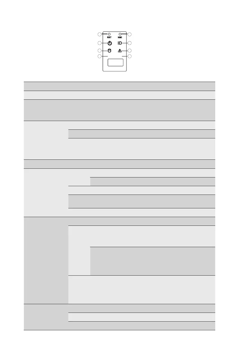
No. Name Color Status Description
1.
Reset Button Press the button to reset the system.
2.
NMI button
Press the button server generates a NMI to the processor
if the multiple-bit ECC errors occur, which effectively halt
the server.
3.
Power button
with LED
Green On System is powered on
Green Blink System is in ACPI S1 state (sleep mode)
N/A Off
• System is not powered on or in ACPI S5 state
(power off)
• System is in ACPI S4 state (hibernate mode)
4.
ID Button Press the button to activate system identication
5.
HDD Status
LED
Green
On HDD locate
Blink HDD access
Amber On HDD fault
Green/
Amber
Blink HDD rebuilding
N/A Off No HDD access or no HDD fault.
6.
System
Status LED
Green Solid On System is operating normally.
Amber
Solid On
Critical condition, may indicate:
System fan failure
System temperature
Blink
Non-critical condition, may indicate:
Redundant power module failure
Temperature and voltage issue
Chassis intrusion
N/A Off
System is not ready, may indicate:
POST error
NMI error
Processor or terminator missing
7/8.
LAN 1/2
Active/Link
LEDs
Green Solid On Link between system and network or no access.
Green Blink Data trasmission or receiving is occuring
N/A Off No data transmission or receiving is occuring
L1 L2
2
4
6
8
1
3
5
7
R152-Z31
R152-Z32
R152-Z33
 Loading...