Hardware Installation - 24 -
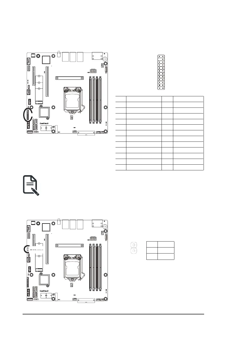
20) FP_1 (Front Panel Header)
Connect the power switch, reset switch, speaker, chassis intrusion switch/sensor and system status indicator
on the chassis to this header according to the pin assignments below. Note the positive and negative pins
before connecting the cables.
The front panel design may differ by chassis. A front panel module mainly consists of power switch,
reset switch, power LED, hard drive activity LED, speaker etc. When connecting your chassis front
panel module to this header, make sure the wire assignments and the pin assignments are matched
correctly.
FP_1
Pin No. Denition Pin No. Denition
1 Power LED+ 13 GND
2 5V Standby 14 LAN1 Link LED-
3 No Pin 15 Reset Button
4 ID LED+ 16 SMBus Data
5 Power LED- 17 GND
6 ID LED- 18 SMBus Clock
7 HDD LED+ 19 ID Button
8 System Status LED(Green) 20 Case Open
9 HDD LED- 21 GND
10 System Status LED(Yellow) 22 LAN2 Active LED+
11 Power Button 23 NMI Switch
12 LAN1 Active LED+ 24 LAN2 Link LED-
2423
21) LAN3_ACT/ LAN4_ACT (LAN3 and LAN4 Active LED Header)
LAN3_ACT
LAN4_ACT
2
1
Pin No. Denition
1 L3_ACT
2 L3_LNK-