EasyManuals Logo

Gill Instruments 1360-PK-022 User Manual

Gill Instruments 1360-PK-022
91 pages
To Next Page IconTo Next Page
To Previous Page IconTo Previous Page
Page #20 background imageLoading...
Page #20 background image
Gill Instruments Ltd
Intrinsically Safe WindObserver Anemometer Page 20 Issue 10
Doc. No. 1360-PS-0001 May 2015
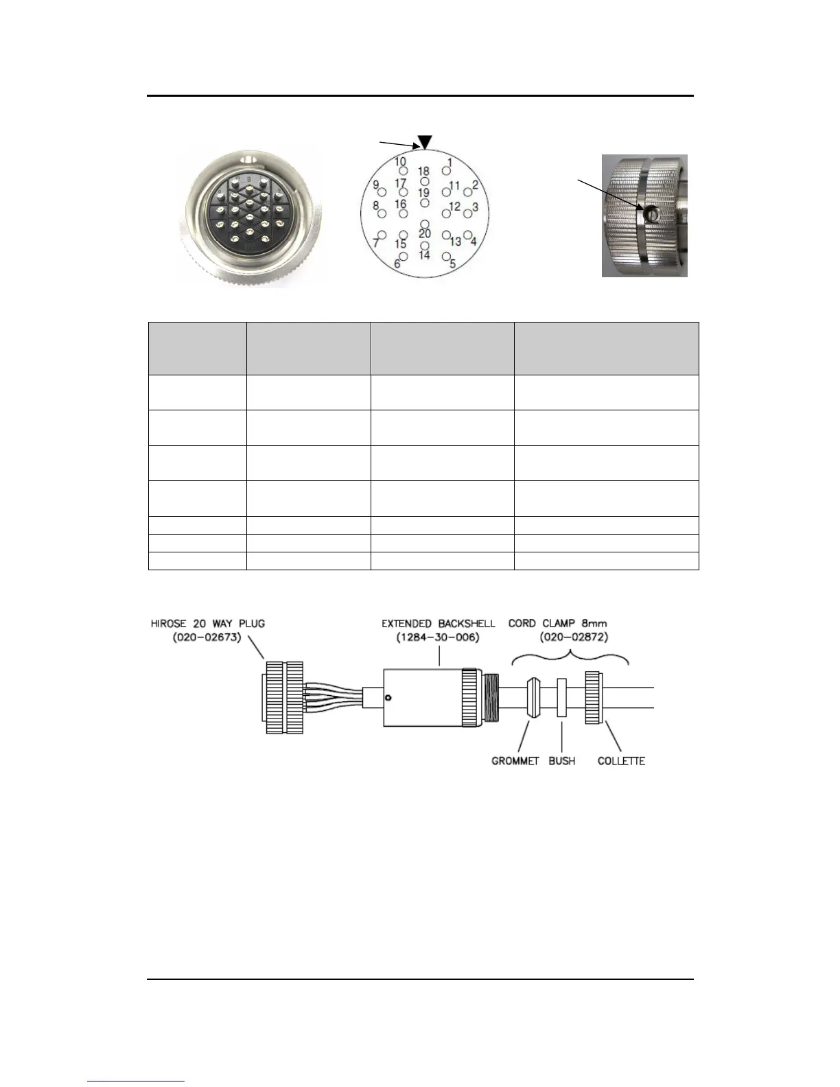
20 Way Connector terminal positions viewed from the solder connection side.
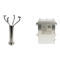
Wiring Connections between the 20 way Anemometer connector and the Power Supply
Interface Box.
20 Way
Connector
Pin Number
Mains
P
ower
Supply Terminal
Number
Low Voltage
Supply J5 Terminal
Number
Anemometer Function
2
24
6
TX+
RS422
Transmit Data
to the Power Box
3
23
5
TX
-
RS422 Transmit Data
to the Power Box
4
21
3
RX+
RS422
Receive Data
to the Anemometer
5
22
4
RX
-
RS422
Rece
ive Data to
the Anemometer
6
26
8
Supply +ve
14
25
7
Supply
ve
-
19 or 20
1 or 2
Cable Screen
Arrange IS WindObserver Connector Parts as Follows.
Align the 20 way plug rotatable ring to allow access of a jeweller’s screwdriver to
remove the miniature grub screw.
Fit parts over the IS cable in the order shown above.
Prepare IS cable for soldering wires to the 20 way connector.
Solder wires to contacts as per the above table.
Screw the extended backshell into the connector (ensure that a sealing ring is
fitted internally) and tighten to a torque of 3Nm
Align the connector ring to allow re-fitting of the grub screw to a torque of 0.2 to
0.3Nm.
Complete assembly of the cord clamp.
Slot Position
Grub Screw

Table of Contents

Questions and Answers:

Question and Answer IconNeed help?

Do you have a question about the Gill Instruments 1360-PK-022 and is the answer not in the manual?

Gill Instruments 1360-PK-022 Specifications

General IconGeneral
BrandGill Instruments
Model1360-PK-022
CategoryMeasuring Instruments
LanguageEnglish

Related product manuals