Gill Instruments Ltd
Intrinsically Safe WindObserver Anemometer Page 55 Issue 10
Doc. No. 1360-PS-0001 May 2015
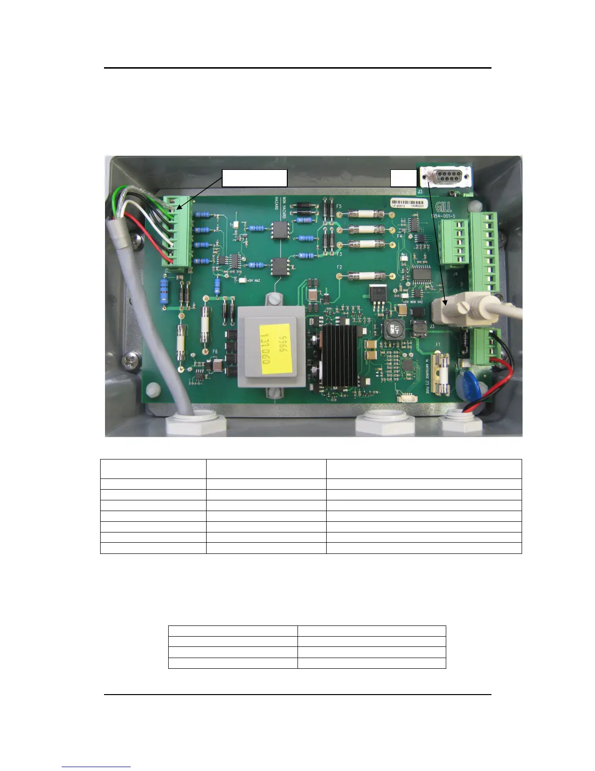
10.6.3 Connections and tests with the Low Voltage Supply Unit
Couple the Intrinsically Safe WindObserver to the power supply unit using a known
working test cable (The 3 metre test cable connections to terminal block J5 are shown
following).
IS WindObserver 3 Metre Test Cable Connection Table to LVPCI Box J5.
RS422 Data +ve to Anemometer (C
ve to Anemometer (Config only)
RS422 Transmit +ve data from Anemometer
Black (Red and Black Pair)
Connect a standard RS232, 9 pin D Type to D Type connector lead to the LVPCI Box
socket J3.
Connect this lead to a PC via its Serial Com port or via an RS232 to USB converter.
PC Serial COM Port Connection to LVPCI Box J3.
9 Way D Type Serial COM Port
 Loading...