Gill Instruments Ltd
Intrinsically Safe WindObserver Anemometer Page 51 Issue 10
Doc. No. 1360-PS-0001 May 2015
10.6 Bench Tests
10.6.1 Alignment Check.
If unexplained data drop outs (code 01, 02, 04 or V code errors) are occurring then it may
be possible that the IS WindObserver transducer arms have become misaligned.
Mechanical Test
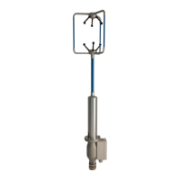
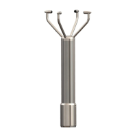
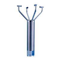
The simplest check for Anemometer alignment is to invert the anemometer with the four
transducers in contact with a flat surface. Gently hold the anemometer cylinder and then
see if it is possible to feel the Anemometer rock on the transducers. If this occurs then it
is likely the transducer arms are misaligned requiring return to Gill Instruments for re-
alignment.
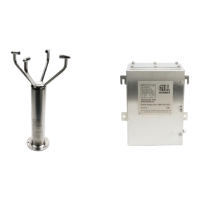
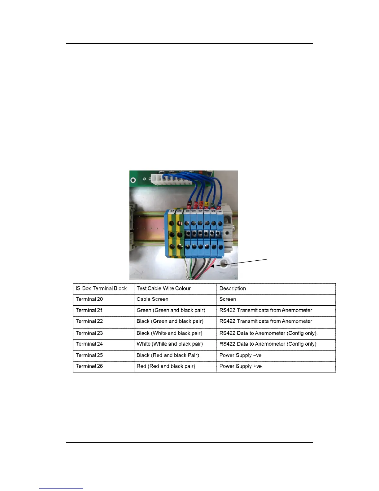
10.6.2 Connections and tests with the Mains Supply Unit
Couple the Intrinsically Safe WindObserver to the power supply using a known working
test cable (The 3 metre test cable connections are shown following).
Anemometer Supply Voltage and Current
With the PCI box powered the Supply Voltage between Terminal 26 +ve and Terminal
25 (-ve) must be between 6v dc to 12v dc. Typically 9v dc.
(If the supply voltage exceeds 12 v dc damage to the Anemometer might result).
The IS anemometer current through terminal 26 will typically be 14mA (maximum.
30mA).
 Loading...