Gill Instruments Ltd
Intrinsically Safe WindObserver Anemometer Page 56 Issue 10
Doc. No. 1360-PS-0001 May 2015
Anemometer Supply Voltage and Current
With the LVPCI box powered, the Supply Voltage between J5 Terminal 8 +ve and
Terminal 7 (-ve) must be between 6v dc to 12v dc. Typically 9v dc.
(If the supply voltage exceeds 12 v dc damage to the Anemometer might result).
The IS anemometer current through J5, Terminal 8 will typically be 14mA (maximum.
30mA).
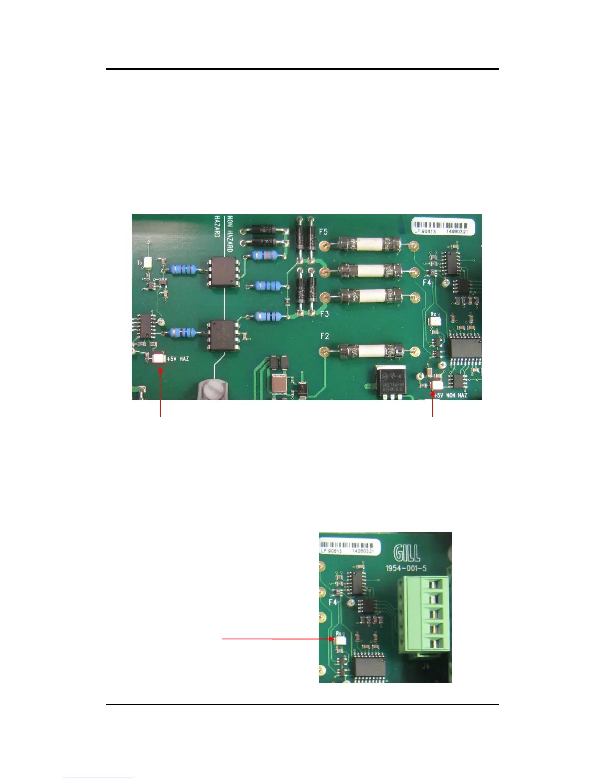
When the IS Power Supply is powered up the +5v NON HAZ and +5v HAZ LED’s will
be illuminated.
Data Tests
With the Sensor connected and outputting data to the PCI box.
Examine the Main PCB and the Red RX LED will be seen to flash on and off at the
sensor output rate (1Hz to 4Hz). This indicates that data is being successfully output from
the IS Anemometer.
 Loading...