WindSonic Doc No 1405 PS 0019 Issue 28 November 2019
30
9.2 Gill format – UV, Continuous
In this mode, the output is given as signed (i.e. positive or negative) speeds along the
‘U’ (= South – North) axis and the ‘V’ (= East – West) axis.
Where:
<STX> = Start of string character (ASCII value 2)
WindSonic node address = Unit identifier
U axis = speed & polarity
V axis = speed & polarity
Units = Units of measure (knots, m/s etc.)
Status = Anemometer status code (see Section 11.5
for further details)
<ETX> = End of string character (ASCII value 3)
Checksum = This is the EXCLUSIVE – OR of the bytes
between (and not including) the <STX>
and <ETX> characters
The WindSonic unit identifier, Units, and Checksum are as described in Section 0 above.
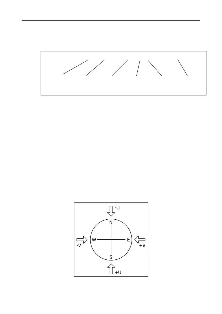
Figure 5 shows the polarity of U and V if the wind components along the U and V axis are
blowing in the direction of the respective arrows.
Figure 5 UV Polarity
<STX>Q, +001.59, - 002.74, M, 00, <ETX> 2D
U axis
speed and
polarity
V axis
speed and
polarity