WindSonic Doc No 1405 PS 0019 Issue 28 November 2019
37
Y2 nnn Setting, User Set Fixed Analogue Output level in an error mode.
The unit will output a fixed Voltage (T1 setting) or fixed milli-amp (T5/T3 settings) signal
on the analogue output with a value depending on the Y2 nnn setting.
nnn is user-selectable value between 000 to 200.
Scale factor for fixed voltage output is 0.025V.
Scale factor for fixed current output is 0.1mA.
Therefore:-
nnn value = Required fixed Error Voltage/0.025 (voltage output setting T1).
nnn value = Required fixed Error Current/0.1 (current output settings T5/T3).
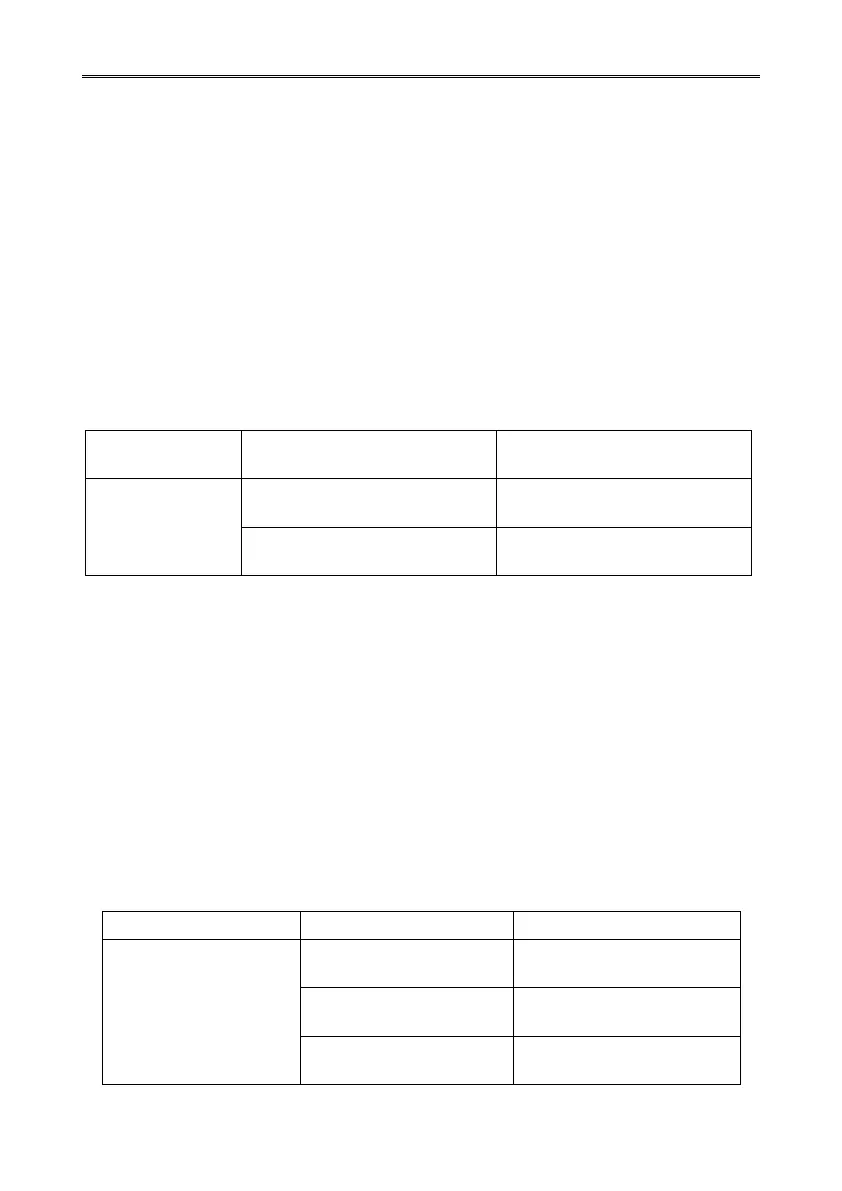
Under data error conditions then by setting the unit for Y2 configuration the analogue
outputs will read a user set error value for the period of the error condition as follows with
the unit in Polar Continuous Output and 0-5v (T1), 0-20mA (T5) and 4-20mA (T3).
Digital Error
Code Output
e.g. 01, 02, 04 etc
Error Condition
nnn x 0.025 v (T1 setting).
Error Condition
nnn x 0.025 v (T1 setting).
Error Condition
nnn x 0.1mA. (T5 & T3 setting)
Error Condition
nnn x 0.1mA. (T5 & T3 setting)
Y3 nnn setting Analogue Output cycles to a user determined level in an error mode.
Under data error conditions the analogue outputs will switch back and forth between a user
determined level (voltage or current) with a value depending on the Y3 nnn setting.
nnn is user-selectable value between 000 to 200.
Scale factor for upper voltage output is 0.025V.
Scale factor for fixed current output is 0.1mA.
Therefore:-
nnn value = Required Error Voltage/0.025 (voltage output setting T1).
nnn value = Required Error Current/0.1 (current output settings T5/T3).
The following table summarises the above reporting conditions with Analogue Outputs set
for Polar Continuous Output and 0-5v (T1), 0-20mA (T5) and 4-20mA (T3).
Digital Error Code
Output e.g. 01, 02, 04
etc.
Cycle 0 – set v – 0 v
at output rate
Cycle 0 – set v – 0 v
at output rate
Cycle 0 – set mA – 0 mA
at output rate
Cycle 0 – set mA – 0 mA
at output rate
Cycle 4 – set mA – 4 mA
at output rate
Cycle 4 – set mA – 4 mA
at output rate