4.3 Electrical Connections
.11.
4. Installation
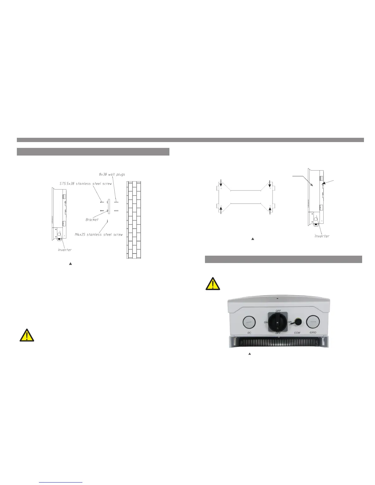
3. Carefully hang the inverter on the upper part of the wall mount bracket by fitting the
hooks into the slot of the bracket. Use M4×25 stainless steel screws and washers
at holes E and F (in Figure 4.2) to secure the mounting hooks to the rear of the inverter.
Figure 4.3 Wall Mount Bracket
A
B
C
D
Inverter
E (F)
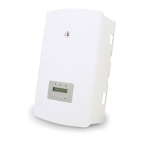
Before connection the wire, please unscrew the four screws on both side of wiring box,
then open the cover.
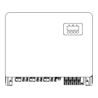
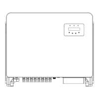
Figure 4.4 Bottom side of inverter
4. Installation
Inverter should be mounted in a vertical position as shown in Figure 4.2. The steps to
mount the inverter on the wall are given as follows:
1. Locate the wall studs in the desired location and align the wall mount bracket over
the studs. Mark the mounting holes. For masonry walls, the mounting holes should be
for a suitable dynabolt type mounting system.
2. MAKE SURE BRACKET IS horizontal. Ensure that the A, B, C, and D mounting holes
(in Figure 4.3) are aligned with the wall's most secure points (e.g. wall studs in case of
clad building materials).
.10.
4.2 Mounting the Inverter
Please use suitable fixings for wall type (e.g. use dynabolts for brick, masonry, etc).
Figure 4.2 Inverter Mounting
WARNING:
Bracket must be mounted vertically on a vertical wall surface.
Please press the cover of wiring box while loose the screw. Otherwise it could
break the screw thread.