4. Comm. & Monitoring 4. Comm. & Monitoring
.27..26.
Internet
Datalogger
PC monitoring
PV Strings
PV Strings
PV Strings
Inverter
Inverter
Inverter
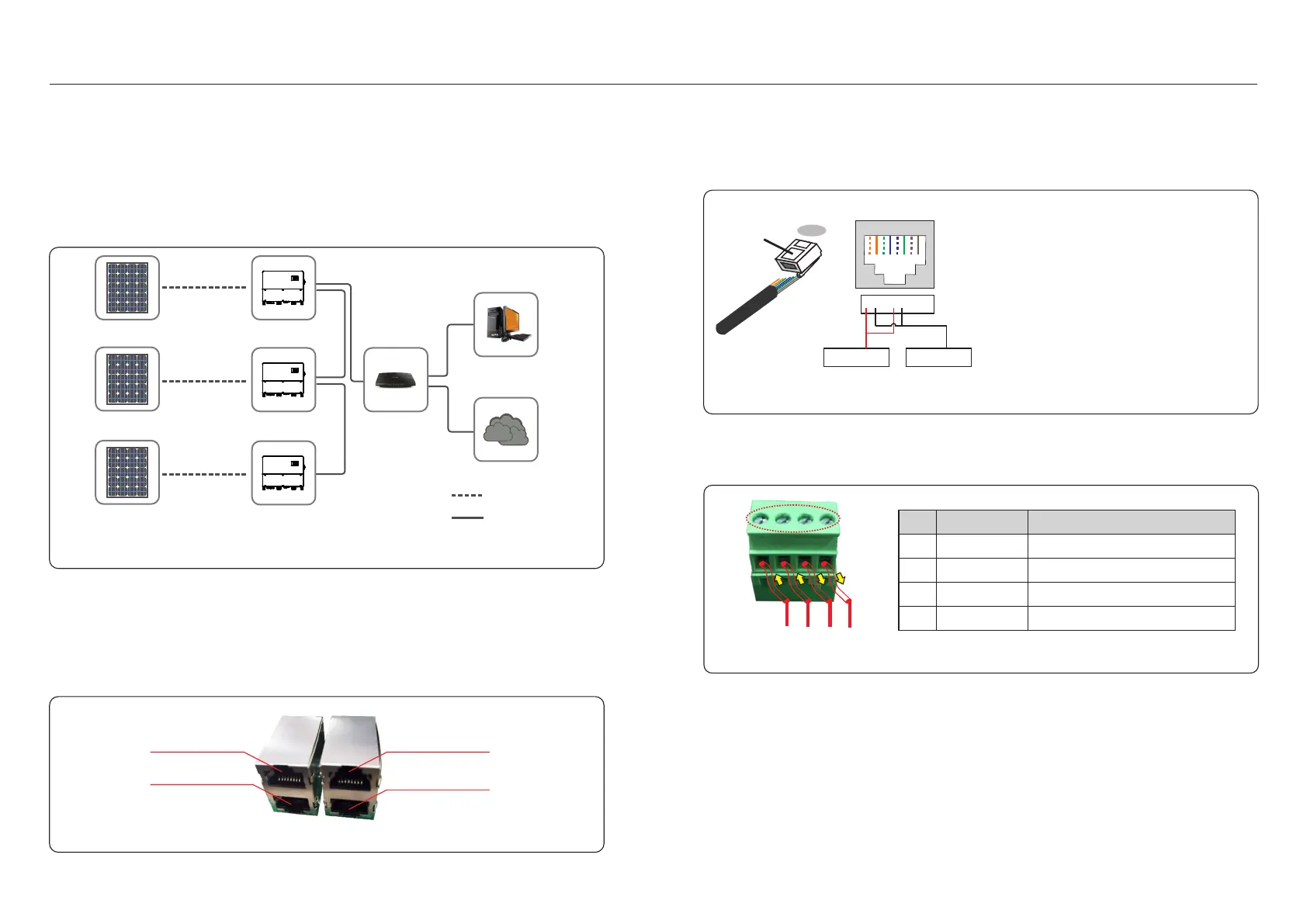
Figure . Multiple inverter monitoring system4 1
DC
RS485/Ethernet
Monitoring system for multiple inverters
Multiple inverters can be monitored through RS-485 and Ethernet daisy chain configuration.
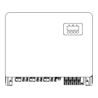
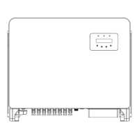
There are 5 communication terminals on Solis 125kW inverter. COM1 is a
4-pin connector reserved for WiFi/Cellular datalogger. COM2 and COM3 are RS485
connection between inverters and both RJ45 and Terminal block are provided for use .
COM4 and COM5 are the Ethernet connection via RJ45.
RS-485 communication uses MODBUS RTU Standard and supports two connection
methods: RJ45 connectors and Terminal board.
1. RS-485 communication through RJ45 connector (See figure 4.2).
CAT 5E outdoor rated (cable outer diameter<9mm, internal resistance≤1.5 Ω /10m) and
shielded RJ45 connectors are recommended.
4.1 RS485 communication
485-IN
485-OUT
Figure 4.2 RJ45 port
Ethernet IN
Ethernet OUT
Figure 4.3 Strip the insulation layer and connect to RJ45 plug
Correspondence between the
cables and the stitches of plug
Pin 1: white and orange ; Pin 2: orange
Pin 3: white and green; Pin 4: blue
Pin 5: white and blue; Pin 6: green
Pin 7: white and brown; Pin 8: brown
Pin 1 with 4 and 2 with 5 are
used for communication connection
Pin 1 and 4 are connected with RS485+A
Pin 2 and 5 are connected with RS485 - B
1--8
RJ45 plug
RJ45terminal
1 2 3 4 5 6 7 8
1 2 3 4 5 6 7 8
R S 4 8 5 + A R S 4 8 5 - B
Use the network wire stripper to strip the insulation layer off the communication cable.
Using the standard wire sequence referenced in TIA/EIA 568B, separate the wires in the cable.
Use a network cable tool to trim the wire. Flatten the wire in the order shown in figure 4.3.
2. RS-485 communication through terminal board.
Figure 4.4
1
2
4
3
The cross sectional area of the cable wire for terminal board connection
should be 0.008-0.06inch. The outer diameter of the cable may be 0.2-0.4inch.
NO.
Port definition
Description
1
2
3
4
RS485A1,RS485 differential signal+
RS485B1,RS485 differential signal-
RS485A2,RS485 differential signal+
RS485B2,RS485 differential signal-
RS485A1 IN
RS485B1 IN
RS485A2 OUT
RS485B2 OUT