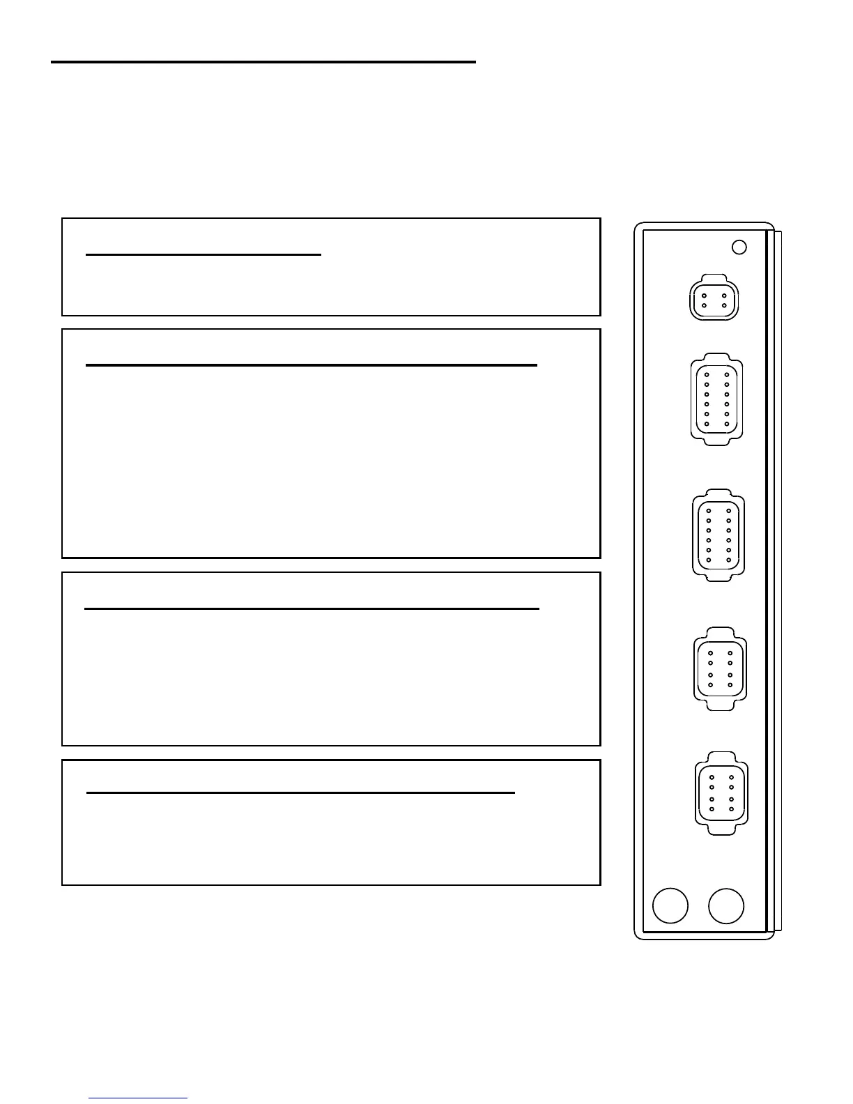
DCPowerConnector(4pin-Gray)
(1)BatteryPositive1
(2)BatteryPositive2
(3)BatteryGround1
(4)BatteryGround2(optional,ifrequired)
PORTGear/StartInterlock/CPEnableConnector(12pin-Gray)
(1)PORTAheadgearPositive(+)
(2)PORTAsternGearPositive(+)
(3)PORTStartInterlock1
(4)PORTIgnition/CPEnable
SwitchInput
(5)EnableSwitchPower
(6)SpareOutput(Com)
(7)SpareOutput(N.O.)
(8)NotUsed
(9)PORTIgnitionOutput
(10)PORTStartInterlock2
(11)PORTAsterngearNegative(-)
(12)PORTAheadgearNegative(-)
STBDGear/StartInterlock/CPEnableConnector(12pin-Gray)
(1)STBDAheadgearPositive(+)
(2)STBDAsternGearPositive(+)
(3)STBDStatInterlock1
(4)STBDIngnition/CPEnable
SwitchInput
(5)EnableSwitchPower
(6)NotUsed
(7)NotUsed
(8)NotUsed
(9)STBDIgnitionOutput
(10)STBDStartInterlock2
(11)STBDAsterngearNegative(-)
(12)STBDAheadgearNegative(-)
PORT/STBDThrottleConnectors-VoltageType(8pin-Black)
(1)Notused
(2)Ref.voltagePos.+
(3)Ref.voltageNeg.-
(4)VoltageOutputSignal
(5)NotUsed
(6)NotUsed
(7)Notused
(8)Chassisground
PortGear
StartInterlock
DCPower
PORT
Throttle
STBD
Throttle
StationCable
Bond
12
11
10
9
8
7
1
2
3
4
5
6
1
2
3
4
8
7
6
5
1
2
3
4
8
7
6
5
1
2
4
3
StbdGear
StartInterlock
12
11
10
9
8
7
1
2
3
4
5
6
NOTE: Jumper #4 to #5 for Dry Contact CP Enable OR Apply 12v DC
positive to #4 for ignition power CP enable.