EasyManuals Logo

Glendinning EEC4 User Manual

Glendinning EEC4
36 pages
To Next Page IconTo Next Page
To Previous Page IconTo Previous Page
Page #5 background imageLoading...
Page #5 background image
Section 1.0 — Installing the EEC4
1
1.0 Installing the EEC4
The installation process includes the following six steps:
STEP 1: Pre-installation planning (the most important part of the process)
STEP 2: Mount the EEC4 Control Processor
STEP 3: Control Head(s) Installation
STEP 4: Station Communication Cable Routing
STEP 5: Engine Compartment Wiring
STEP 6: Operational Test
1.1 Pre-Installation Planning
Before beginning the installation of the Glendinning EEC4 System, it is very important that some
thought be given to the overall installation. The following should be considered:
Control Processor location
Power / Battery supply
Station Communication Cable routing
STBDEngine
PORTEngine
Circuit
Breaker
Circuit
Breaker
Batte
ry
#1
Battery
#2
+
+
-
-
DCPo
w
erHarness
StationCable
ToStartInterlockCntr.
MainHelmStation
Bondsystem
toveselbond
per
ABYCs
pe
s.
Terminating
Resistor
Batteriesmusthave
acommonground
ToThrottleCntr.
GearHarness
EngineHarness 20
'
Sta
tion
STBDThrottle PORTThrottle
STBDGear
PORTGear
DCPWR
Bond
EngineH
a
rn
e
ss 2
0'
Terminating
Resistor
ToIgn.SwitchCntr.
TopMountControl
GearHarness
ExistingJumper
inenginecntr.
ToStartInterlockCntr.
ToThrottleCntr.
ToIgn.SwitchCntr.
ExistingJumper
inenginecntr.
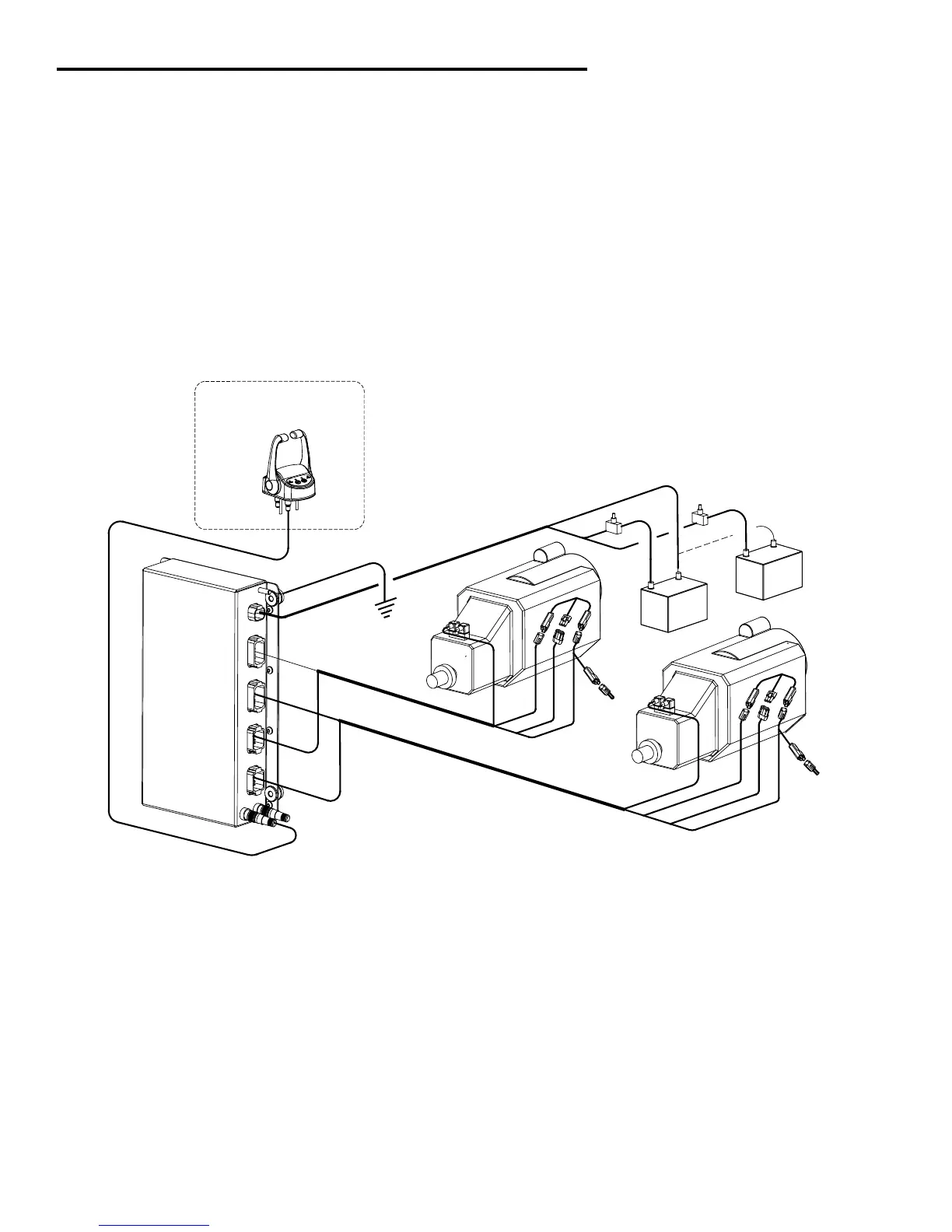
Installation Preview
For a larger version of this drawing
see Appendix (sec. 2.0, pg.17)

Questions and Answers:

Question and Answer IconNeed help?

Do you have a question about the Glendinning EEC4 and is the answer not in the manual?

Glendinning EEC4 Specifications

General IconGeneral
BrandGlendinning
ModelEEC4
CategoryControl Unit
LanguageEnglish