EEC4 Installation Manual
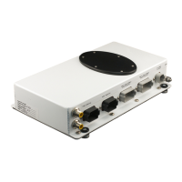
Control Processor Location
Environmental conditions—The CP is designed to be located in the
engine compartment of a typical boat. It can be mounted in any position
— horizontally on the overhead or deck or on one of the engine compart-
ment walls. Although the CP has been designed to operate in ambient
temperature conditions of up to 70 C (158 F), as far as possible, the CP
should not be exposed to extreme temperature conditions (ie, touching
any part of the engine exhaust). The CP is not designed for direct water
impingement and therefore should not be located where it may be
sprayed with water or with connectors facing upward.
Accessibility—Approximately 15 cm (6 inches) of clearance should be
maintained at the side of the CP where the connection plugs are locat-
ed to provide for plug installation and removal.
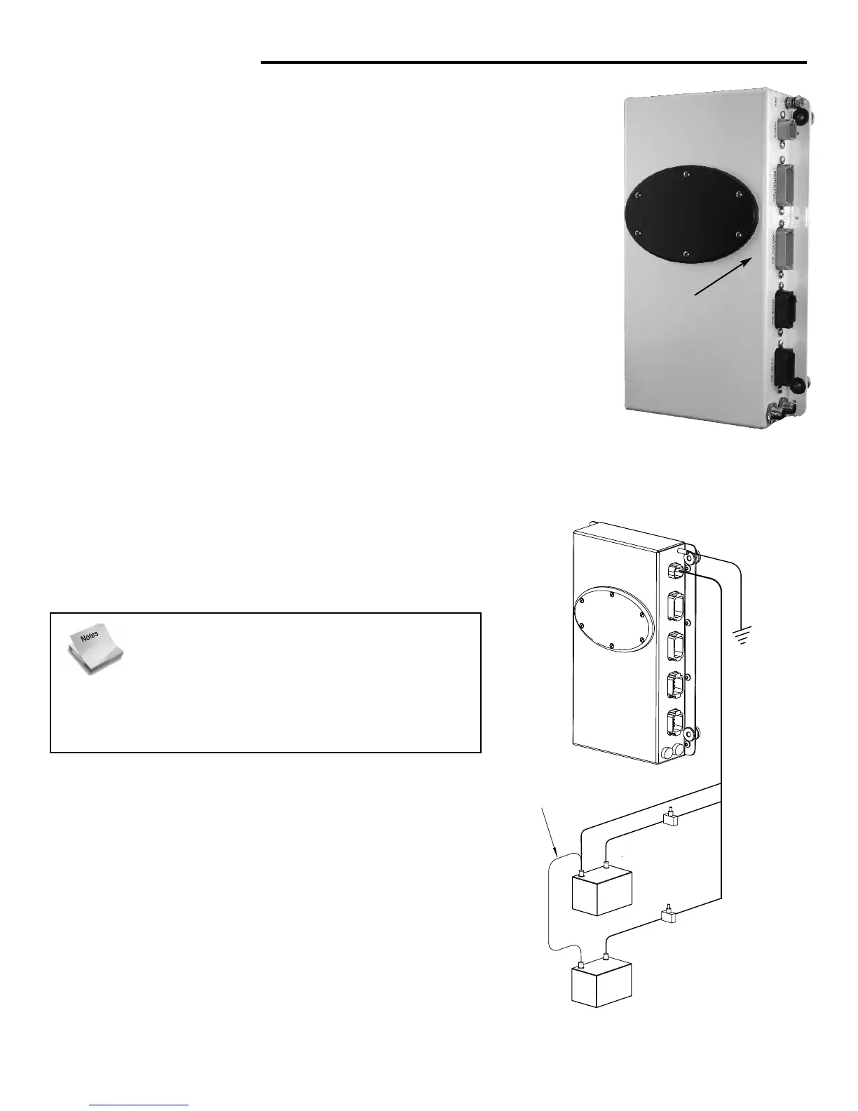
Power Supply
In the installation of any electronic device, the source of power is one of the most important factors to
consider during the installation. The EEC4 has been
designed to be connected to two (2) 12 VDC power
sources, although it can operate on only a single power
source.
Ensure that the power supply to the control system
includes the following:
— Battery sources should be independent, not 2 batteries
connected in parallel.
— Circuit protection (fuse or circuit breaker) should be
installed at the point where the CP power harness is con-
nected to the battery / power source. Use 10 amp circuit
protection.
— The battery ground wire should be connected to one of the batteries. Verify that the battery ground
wires are connected together elsewhere on the vessel.
perABYCspes.
s.
10amp.
10amp.
2
Proper clearance
should be planned
for the connection
side of the Control
Processor for the
various harness
connections
(6” MINIMUM).
IMPORTANT! — Although the EEC4 system can
operate on a single battery power source, con-
necting to two (2) separate battery sources is
STRONGLY RECOMMENDED. If the EEC4 system
is only connected to a single battery power source, intermit-
tent drops in battery voltage — perhaps during engine start
— can cause intermittent failures of the EEC4 system.