EEC4 Installation Manual
The Dual Station Layout illustrates how both control stations are connected to the control processor
by separate cables. An alternative installation would be to connect the station communication cable for
the upper Control Head to the lower Control Head instead of the Control Processor (as shown). A ter-
minating resistor is plugged into the open CANbus connections that do not have a Station
Communications cable connected to them.
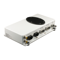
Single Station Layout
Single cable connects control head to control processor.
Terminating resistor installed
at open communications port
at control head.
Terminating resistor installed at
open communications port at
control processor.
4
Dual Station Layout
Communication cable plugged into
each port of the control processor:
1 cable — lower helm station
1 cable — upper helm station
Terminating resistor installed at
open communications port at
control heads.