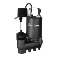
ease the pump out of the connector. You
may need to loosen the hose clamps on
the backup pump.
9. While you have the pump apart, this would
be a good time to replace the check
valves. Contact Glentronics, Inc. to order
bleed hole is required to help prevent an air
lock within the system.
10. Remove the screws from the strainer on
the new primary pump and discard them
before you place it on the sump foot. You
will need to thread the old screws through
the foot, the strainer and into the pump.
11. Line up the discharge pipes parallel to each
other and start with the top screw. Once the
top screw is replaced, the other screws will
line up with the holes. Tighten all the screws.
12. Ease the pump back into the no-hub
connector and tighten the hose clamps.
13. Lower the pump back into the pit by the
handle of the primary pump.
14. Connect the top of the system to the no-
hub coupling and tighten the hose clamp.
15. Connect the backup pump to the back of
the backup control unit
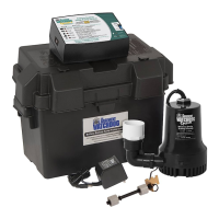
16. Connect the battery wires to the battery
posts, RED to the POSITIVE (+) post and
BLACK to the NEGATIVE (-) post. Replace
the cover on the battery box.
17. Plug the power cord from the backup
control unit into the outlet. You should
provide additional protection to the system
by using a surge protector.
18. Plug the primary pump into the receptacle
on the blue Enhanced controller and then
plug the power cord from the controller
into the wall outlet.
19. If any of the alarms are sounding, press
the RESET button for 1 second.
20. After the primary pump is replaced, be
the sump pit with water and observing the
pump through several full cycles.
5
Battery power level
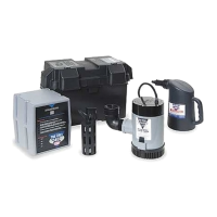
Your Pro Series combination sump pump
system has a gauge which will report the level
of charge remaining in the battery. As the
battery’s energy is depleted during operation
without AC power or simply by aging, the
gauge will indicate the percent of charge
remaining in the battery. Should the level drop
below 25%, the “Battery problem” indicator will
light up and the alarm will sound.
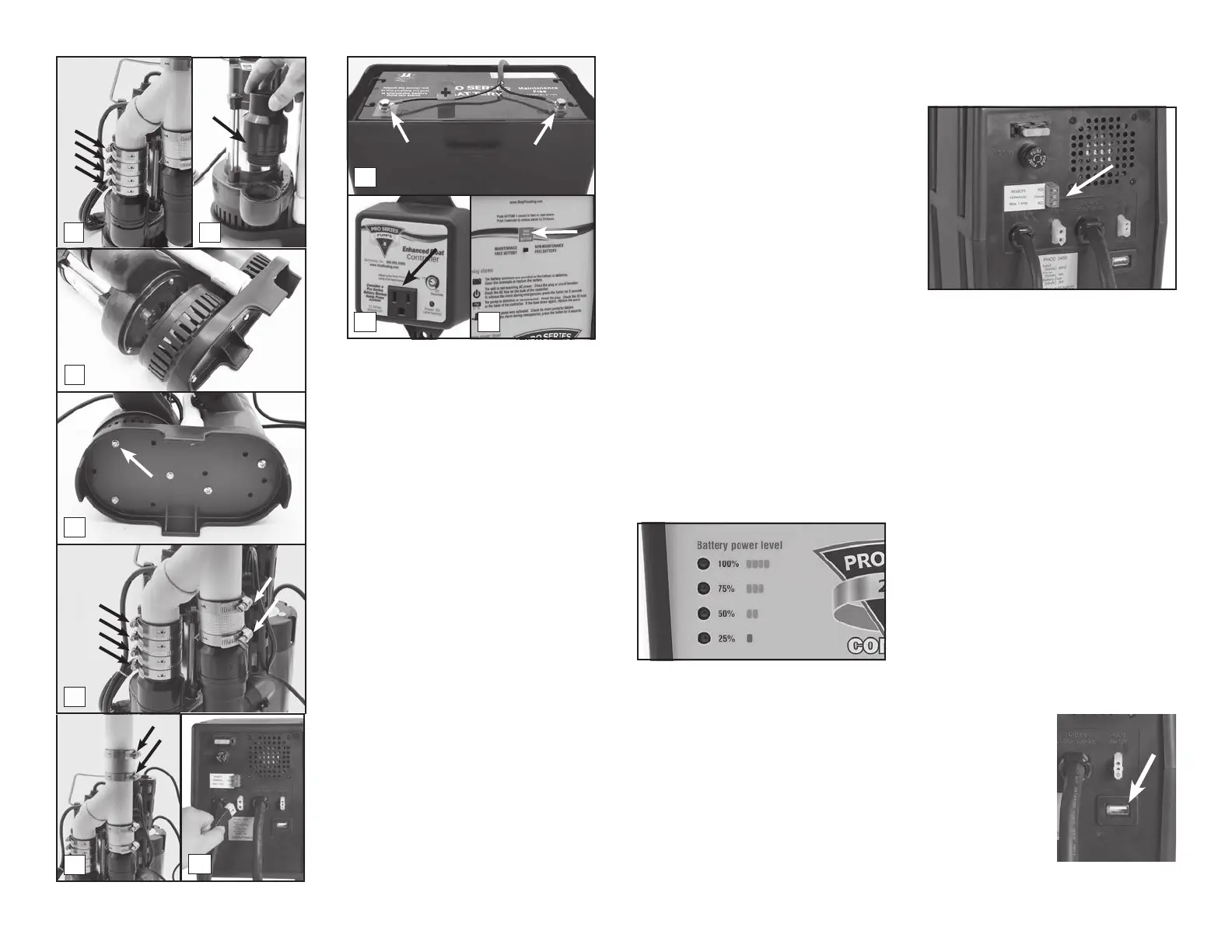
Remote Notication
THE REMOTE TERMINAL
The Pro Series 2400 can be connected to
a home security system or other alarm
devices to alert you to a problem or required
maintenance.
INSTRUCTIONS FOR CONNECTING
A REMOTE ALARM
The terminal is located on the back of the
control unit. There are three (3) positions
for wire connections on the terminal: N.C.
(Normally Closed), N.O. (Normally Open), and
Common.
Check your security system or alarm to
determine whether an open (no contact) or
closed (making contact) connection is needed
to activate the alarm.
The security system will provide two
connection terminals. You will need to extend
wires from the security system to the Pro
each. Connect either wire to the common
terminal. To secure the wire into the terminal,
insert the exposed wire into the hole on the
back of the terminal next to the screw marked
Common. Turn the screw a few turns to lock
in the wire.
If the security system requires a closing
of a contact to activate the alarm, secure
the other wire in the terminal hole labeled
N.O. (Normally Open). If the security system
requires an opening of a contact, secure
the wire in the terminal hole labeled N.C.
(Normally Closed).
USB DATA PORT
This system has been updated with a USB port
on the back of the controller. The purpose of
this port is to allow
communication
with the Pro Series
CONNECT Module.
DO NOT connect any
other device to the
USB data port other
CONNECT Module.
Page 10
8
9
10
14
11
12
18 19
15
16
Negative
Bolt
Positive
Bolt
 Loading...