15
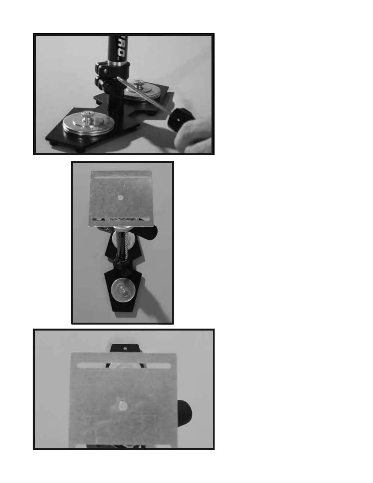
In the next procedure you are going to
align the BOTTOM PLATE so that its
front edge is parallel to the front edge
of the BASE PLATFORM. The result
of this correct alignment will make your
Glidecam 2000 Pro look like Photo 29B
and Photo 29C. Photo 29C is taken from
the point of view of looking straight
down at the front of the Glidecam 2000
Pro.
There are two ways to create this correct
alignment. The first and easiest is to
just loosen the “Adjustment Knob” on
the TELESCOPING CLAMP and then
rotate the parts until they are correctly
aligned as in Photos 29B and 29C. Then
simply retighten the
“Adjustment Knob”.
Remember to leave about 1 inch of
TELESCOPING POST showing below
the TELESCOPING CLAMP as before.
The second way to correctly align the
parts (see Photo 29A) is to use a Phillips
Screwdriver to loosen the “Screw” on the
top part of the TELESCOPING CLAMP
until you can
rotate the parts so they are
correctly aligned as in Photos 29B and
29C. Then simply retighten the “Screw”.
NOTE: The second method of alignment
is better because it keeps the
TELESCOPING CLAMP’S “Adjustment
Knob” aligned correctly as previously
shown in Photo 24, and having the
TELESCOPING CLAMP’S “Adjustment
Knob” aligned correctly, while not
technically needed to make your Glidecam
2000 Pro function correctly, does make it
easier to reach the Knob later when you
use it.
29A
29B
29C