Glidermatic GRD+ Installation Instructions & owner’s manual Page 5
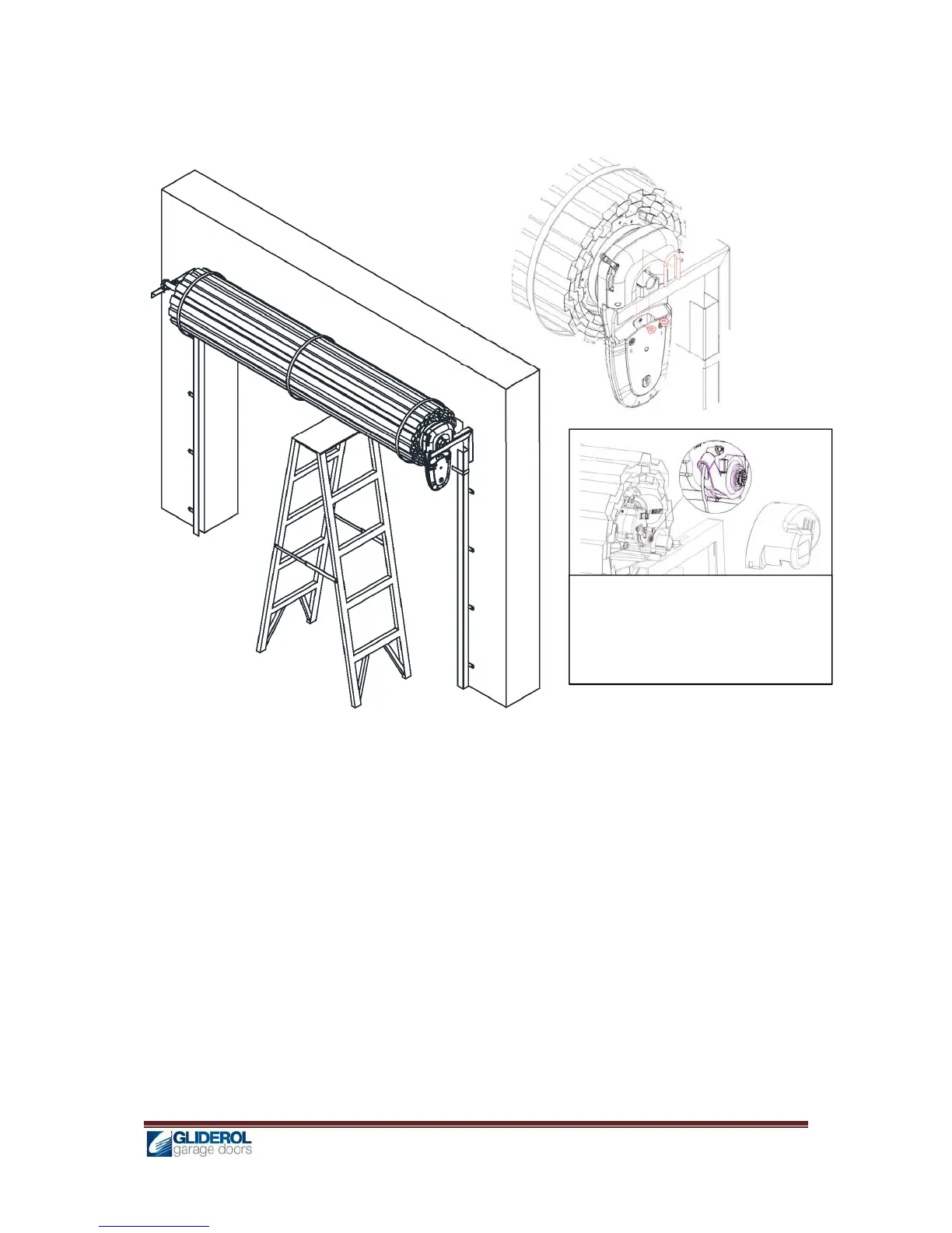
h) Replace right hand side wall mount bracket (Fig 4)
i) Carefully remove the support from the door and rest spindle on the wall mount bracket
j) Locate the Drive unit on the bracket and fit ‘U’ bolt provided in the fitting kit. Tighten the ‘U’ bolt
with two nuts provided (Fig 4a).
k) Fit Anti coning collar to the opposite end of the door to avoid sideways movement of the drum
wheel.
Alternate Method: On smaller size doors the GRD+ unit may be installed without removing and
replacing the bracket. After step (d) carefully lift the roller door from the bracket enabling GRD drive
unit to slide on to the spindle of the door. Ensuring the unit’s fork is properly engaged with the spoke
of drum wheel carefully rest the door on the spindle and follow consecutive steps from (j)
l) Insert manual release cable into the manual release lever in the motor and secure it by
tightening the lock screw. (Fig 5)
Note: If bracket is in the way of the manual release cable, a small hole may be drilled on the bracket and manual
release cable may be fitted by passing it through the bracket hole and then into the manual release lever and
secured by lock screw.
Replace this picture showing G+
roller unit manual release.
Fig: 5
Fig: 4
Fig: 4a