0020107233_00 - 06/11 - Glow-worm
INSTALLATION
- 19 -
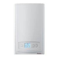
Diagram 7.1
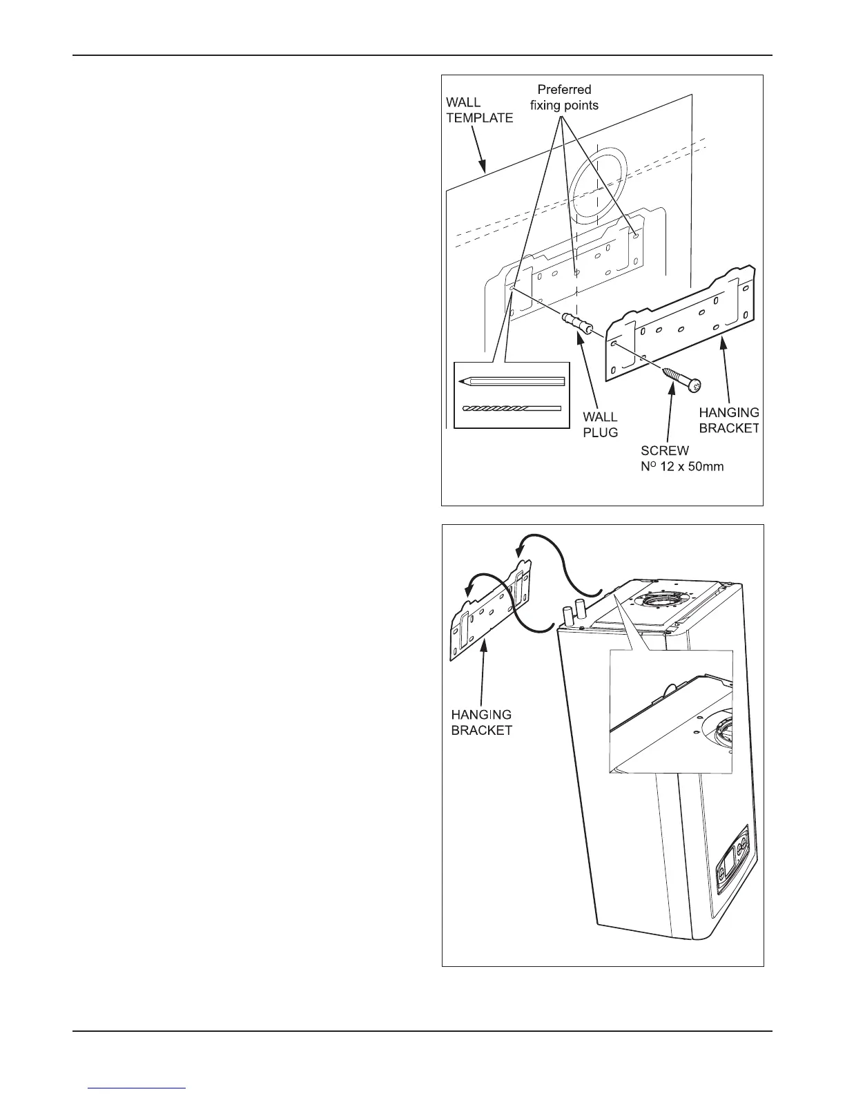
Diagram 7.2
13506
13503
Reposition the wall template over the ue hole and mark
the position of the xing holes for the hanging bracket, see
diagram 7.1.
Mark and drill the xing holes and secure the hanging bracket
which is supplied in the polystyrene base pack.
Due to the varied site conditions we do not supply
xings and advise that the installer should supply those which
are suitable.
With regards to the Manual Handling
Operations, 1992 Regulations, the following lift operation
exceeds the recommended weight for a one man lift, refer to
section 15 Manual Handling.
Lifting the boiler into position, lean the top of the boiler slightly
to the wall and position just above the hanging bracket. Lower
the boiler slowly and engage onto the hanging bracket, see
diagram 7.2.
Remove the polystyrene base support.
 Loading...


