0020107233_00 - 06/11 - Glow-worm
INSTALLATION
- 23 -
Close the cartridge and secure with the previously removed
screw.
Push the electrical cartridge into the interface housing on
completion of the wiring, see diagram 9.3.
Secure with the two cartridge retaining screws provided in the
cartridge body.
Carry out preliminary electrical system checks as below:
1. Test insulation resistance to earth of mains cables.
2. Test the earth continuity and short circuit of cables.
3. Test the polarity of the mains.
If you require to test the appliance refer to section 12.
13301
Diagram 9.3
CARTRIDGE
FIXING
SCREWS
At the time of commissioning, complete all
relevant sections of the Benchmark Checklist located in the
inside back pages of this document.
The commissioning should be carried out by a
approved at the time by the Health and Safety
Executive and in accordance with the current issue of
BS6798.
Make sure that the system has been thoroughly ushed
out with cold water and that all cleanser, if used, has been
removed.
Isolate the boiler from the mains electrical supply.
Test for gas tightness and purge air from the gas supply.
Before starting the boiler check that all ue
connections are secure and sealed correctly.
With the gas isolation valve closed and with no demand from
any external controls.
1. Fill the heating system.
Sealed system only - ll the system to a pressure of 1.0bar.
2. Vent all air from the system - repeat as necessary until the
system is full and all the air has been vented.
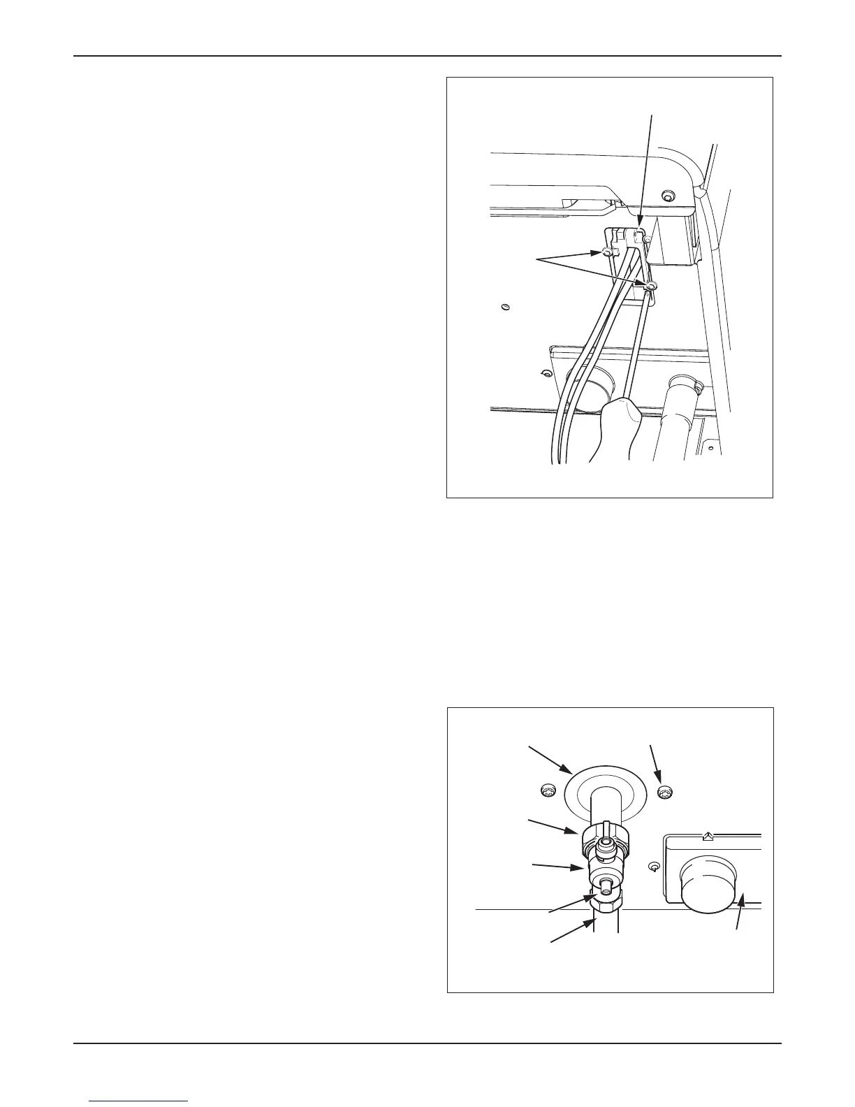
The gas valve is factory set for natural gas (G20) and should
need no adjustment. Turn on the gas supply at the isolation
valve, see diagram 10.1. Check the supply pressure at the
pressure test point is 20mbar.
15704
Diagram 10.1
GAS
SUPPLY PIPE IN
GAS PIPE BRACKET
SECURING SCREW
GAS
SERVICE
ISOLATION
VALVE
UNION
NUT
SEALING
GROMMET
CONDENSE TRAP
& SIPHONIC DRAIN
PRESSURE TEST
POINT

 Loading...


