0020107233_00 - 06/11 - Glow-worm
INSTALLATION
- 22 -
This appliance must be earthed.
● This appliance must be wired in accordance with these
instructions. Any fault arising from incorrect wiring cannot be
put right under the terms of the Glow-worm guarantee.
● All system components must be of an approved type.
Electrical components have been tested to meet the
equivalent requirements of the BEAB.
● Do not interrupt the mains supply with a time switch or
programmer.
● Connection of the whole electrical system and any heating
system controls to the electrical supply must be through a
common isolator.
● Isolation should preferably be by a double pole switched
fused spur box having a minimum contact separation of
3mm on each pole. The fused spur box should be readily
accessible and preferably adjacent to the boiler. It should be
identied as to its use.
● A fused three pin plug and shuttered socket outlet may be
used instead of a fused spur box provided that it is not used in
a room containing a xed bath or shower.
● The boiler is suitable for installation in bathroom zones 2
and 3.
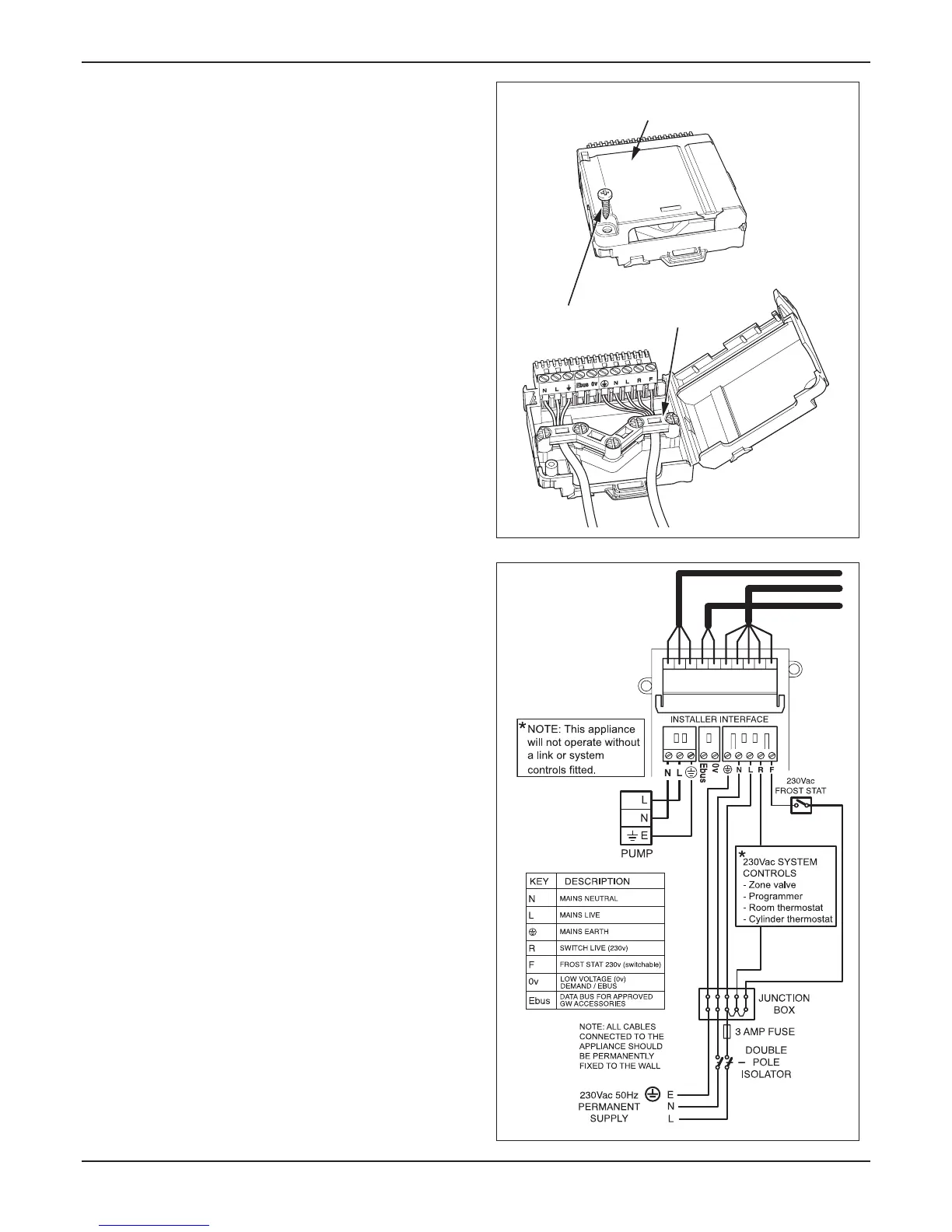
Remove the electrical cartridge from the ttings pack.
Remove the securing screw to open the cartridge, see
diagram 9.1.
: There are two screws supplied loose in the electrical
cartridge, these will be required to secure the cartridge into
the electrical interface housing.
Slacken the cable strain relief screws in the electrical
cartridge, see diagram 9.1.
Route the mains supply and system cables through the strain
relief and connect to the relevant plug , see diagram 9.2.
Ensure that a separate pump supply cable is routed through
the strain relief and connected to the relevant plug, see
diagram 9.2.
Slacken the cable strain relief and route the pump electrical
supply cable and connect as shown in diagrams 9.1 and 9.2.
If you are tting the Glow-worm Options Board Kit, please
refer to the instructions supplied with the kit for the system
wiring.

 Loading...


