0020107233_00 - 06/11 - Glow-worm
INSTALLATION
- 25 -
These boilers are fully modulating, therefore it is not
necessary to range rate them, however, if desired, you can
adjust the 38hxi boiler in 1kW increments between 10 and
maximum output of your appliance, as described below.
Please refer to the table to check the gas rates.
a) Press and hold the ‘MODE’ button for 5 seconds. The
display will change to ashing ‘0’.
b) Use the heating ‘+’ or ‘-’ buttons to scroll to 96 (This is
the installer level access password).
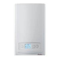
c) Press ‘MODE’ to conrm, see diagnostic display 1.
d) Press ‘MODE’ to change to the heating load value, see
diagnostic display 2.
e) Use the heating ‘+’ or ‘-’ buttons to set the heating design
value required.
f) Press the ‘MODE’ button to conrm the diagnostic number
ashes, see diagnostic display 1.
g) Hold ‘MODE’ for 5 seconds to save and exit.
Check that all external controls are calling for heat. The
boiler will re automatically. Fully open all radiator valves, ow
control valve ‘A’ and bypass valve ‘B’, see diagram 5.3.
Balance the radiators as required and if tted adjust valve ‘A’
to give the required system differential. Turn off all radiators
that can be shut off by the user and check to see if less than
the maximum differential allowed of 20
O
C can be achieved
across ow and return.
Allow the system to reach maximum temperature then switch
off the boiler by isolating from the electrical supply.
The pump overrun will continue for 5 mins.
Drain the entire system rapidly whilst hot, using the drain taps
at all the low points of the system. Fill and vent the system as
described previously.
Lock or remove the handle from control valve ‘A’ to prevent
unauthorised adjustment.
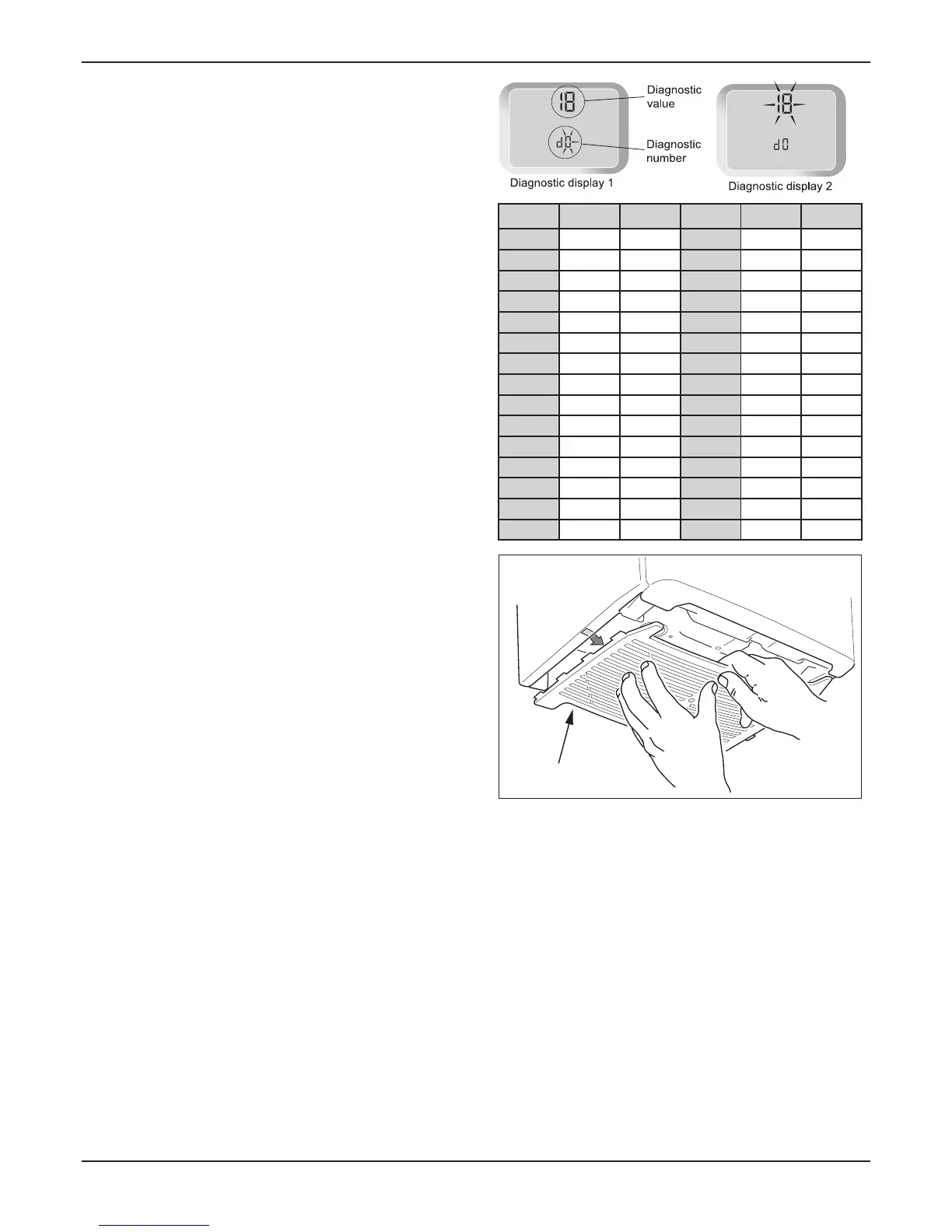
Fit the base coverplate, see diagram 10.3.
Ensure that the magnetic lighting instruction label is placed on
the surface of the boiler casing
It is a requirement that the “Benchmark” Installation,
Commissioning and Service Record is completed and left with
the user.
it is necessary to complete a “Declaration of Conformity” to
indicate compliance to I.S.813. An example of this is given in
the current edition of I.S.813.
● Demonstrate, then instruct the User about the lighting
procedure and heating system controls operation.
● Advise that to ensure the continued efcient and safe
operation of the boiler it is recommended that it is checked
and serviced at regular intervals. The frequency of servicing
will depend upon the installation conditions and usage, but in
general, once a year should be enough.
● Draw attention, if applicable, to the current issue of the Gas
Safety (Installation and Use) Regulations, Section 35, which
imposes a duty of care on all persons who let out any property
containing a gas appliance in the UK.
● The user shall not interfere with or adjust sealed
components.
● It is the Law that any servicing is carried out by a
approved at the time by the Health and
Safety Executive.
COVER PLATE
Diagram 10.3
13540
● Advise the user that, like all condensing boilers this
appliance will produce a plume of condensation from the ue
terminal in cool weather. This is due to the high efciency and
hence low ue gas temperature of the boiler.
● Advise the user of the precautions necessary to prevent
damage to the system, boiler and the building, in the event of
the heating system being out of use during frost or freezing
conditions.
● Advise the user that the permanent mains electrical supply
SHOULD NOT be switched off, as the built in frost protection
and pump saver program will not operate.
● Advise the User if the mains electricity and gas are to be
turned off for any long periods during severe weather, it is
recommended that the whole system, including the boiler,
should be drained to avoid the risk of freezing.
: Contact your installation/servicing
company as draining, relling and pressurising MUST be
carried out by a approved at the time by
the Health and Safety Executive.
● Leave these instructions and the ‘Benchmark’ Installation,
Commissioning and Service Record with the user.
13450
13451
kW m3/hr ft3/hr kW m3/hr ft3/hr
24 2.5 88.3
38 4.06 143 23 2.4 84.8
37 3.9 138.5 22 2.3 81.2
36 3.8 135 21 2.2 77.7
35 3.7 131 20 2.1 74.2
34 3.6 127 19 2.0 70.6
33 3.5 124 18 1.9 67.1
32 3.4 120 17 1.8 63.6
31 3.3 117 16 1.7 60.0
30 3.2 113 15 1.6 56.5
29 3.1 109.5 14 1.5 53.0
28 3.0 106 13 1.4 49.5
27 2.9 102.4 12 1.3 45.9
26 2.8 98.9 11 1.2 42.4
25 2.6 91.8 10 1.12 38.9
 Loading...


