13862
4.06 143
3.02 107
2.58 91.1
2.00 70.6
1.61 57
1.29 45.6
0.67 23.8
0.56 19.8
0.56 19.8
0.53 18.7
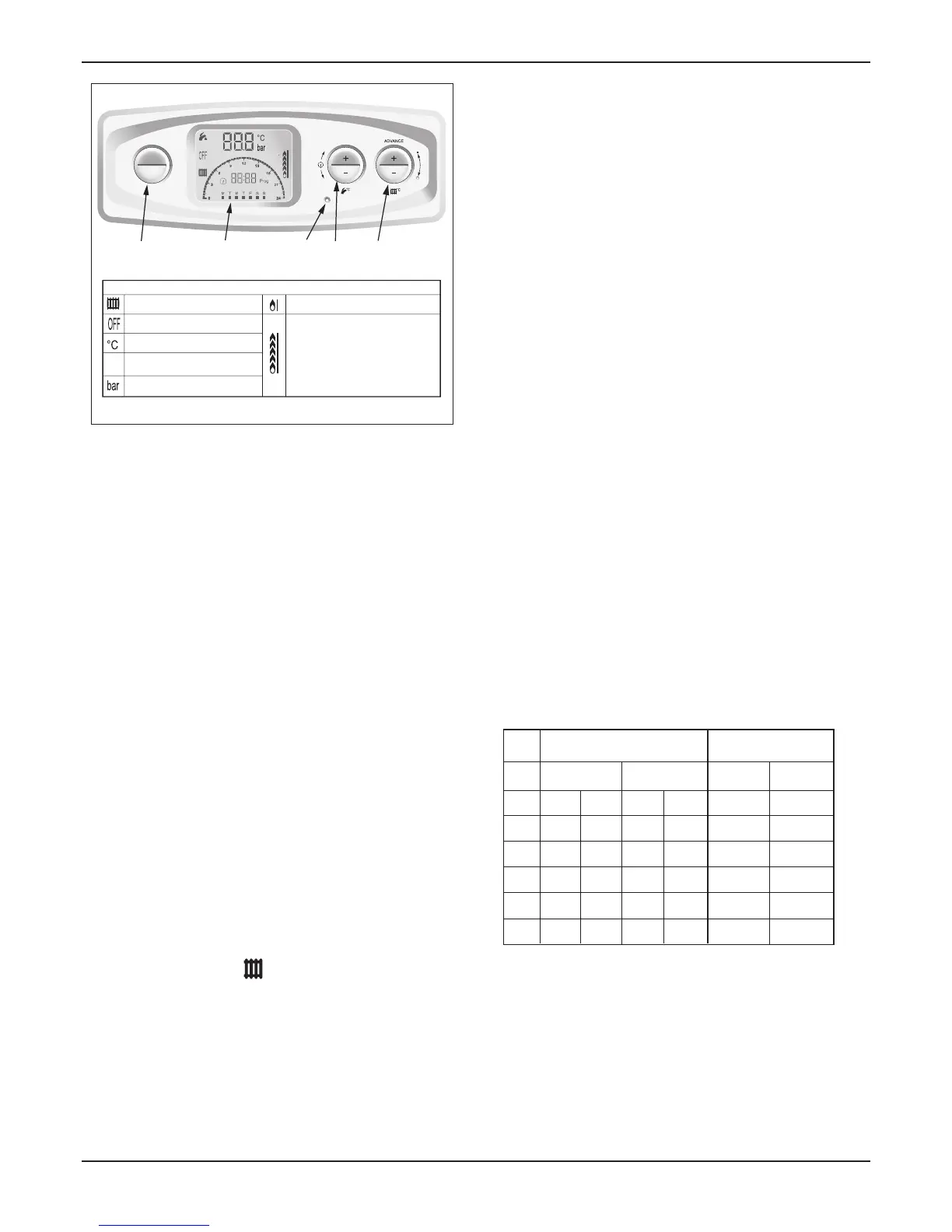
12hxi
15hxi
18hxi
24hxi
30hxi
38hxi
GAS RATES (G20)
MIN
m
3
/h ft
3
/h
MAX
m
3
/h ft
3
/h
0.53 18.7
0.53 18.7
2.98
2.22
1.9
1.47
1.19
0.95
0.52
0.41
0.41
0.39
GAS RATES (G31)
MIN
kg/hr
MAX
kg/hr
0.39
0.39
Model
approx. after 10 mins from cold approx. after 10 mins from cold
● the appliance has been installed in accordance with the
instructions.
● the integrity of the ue system and ue seals.
● the integrity of the appliance combustion circuit and
relevant seals.
● that all internal/external controls are calling for heat.
● the gas service isolation valve, diagram 10.1, is open.
As an option, a chargeable boiler performance and function
service can be provided by Glow-worm Service by calling
telephone No. 01773 828100.
See section 10.10.
: If you have tted a Glow-worm Options Board Kit,
please refer to the instructions supplied with the kit for
completion of commissioning.
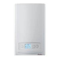
Refer to diagram 10.2
1. With no demand from any external controls, switch on the
electrical supply to the boiler.
Open the gas service isolation valve, see diagram 10.1.
2. Select your required function by pressing “ Mode “, scroll
through your options and select one of the following:-
Central heating.
Boiler functions ALL switched off. “OFF”
3. Turn ON your external controls and select the room
temperature required.
The boiler will operate automatically.
: The display will indicate the Heating system water
temperature or a fault code if in a fault condition.
The supply from the governed meter must be of adequate
size to provide a steady inlet working pressure of 20mbar (8in
wg) at the boiler. On completion, test the gas installation for
tightness using the pressure drop method and suitable leak
detection uid, purge as necessary.
Due to the modulating operation of the boiler and
the need to check the gas inlet pressure and measure the
gas rate at maximum rate, it will be necessary to force it to
maximum.
Press the “reset” button on the controls fascia, release
and immediately press and hold in the “+” button. After
approximately 5 seconds “Hi” will be displayed. Pressing
the mode button when “Hi” is selected will force the boiler
to maximum rate, the display will ash between “Hi” and the
“default display” this will indicate the boiler has been forced to
maximum.
Operational Gas Inlet Pressure
With ALL other gas appliances operating, check the
operational supply pressure at the gas service isolation valve
test point, see diagram 10.1.
The nominal supply pressure for Natural Gas (G20) is 20mbar.
The nominal supply pressure for LPG (G31) is 37mbar.
Turn the taps and appliances off, then disconnect the pressure
gauge.
Additionally the safe nominal maximum heat input of the
appliance can be achieved at an inlet pressure down to
15mbar.
The cannot be measured and
is not used to measure the gas rate.
Gas Rate
Make sure that ALL other gas burning appliances and pilot
lights are off.
Check the gas rate using the gas meter test dial and stop
watch, at least 10 minutes after the burner has lit, see table
below for approximate rates.
In communal or LPG installations where the gas rate cannot
be measured it is acceptable to measure the combustion rate
as described in the servicing section.
On completion, press the “mode” and “+” buttons
simultaneously, this will reset the boiler.
 Loading...


