29
10.11 Direct Rear ue - Telescopic
Part No. A2043500.
Refer to diagram 10.19 for kit contents.
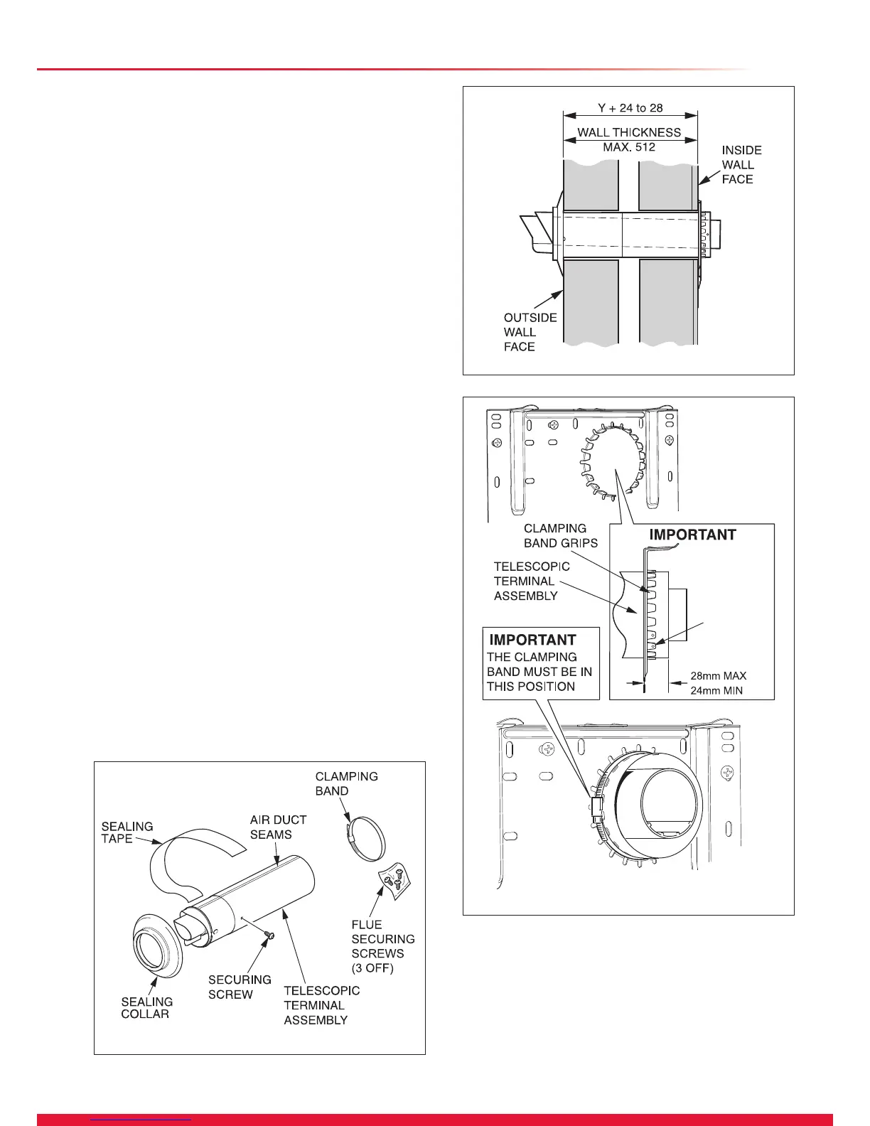
10.12 Flue Length
Measure the distance from the outside wall to the inside wall
face. This measurement must not exceed 512mm (465mm
if the upward piping kit is used). If the dimension is less than
291mm DO NOT cut the ue, it can project to a maximum of
600mm, see diagram 10.15.
10.13 Flue Fitting
Set the ue to the required length ‘Y’ plus 24mm min to 28mm
max, see diagram 10.20, ensure the air duct seams line up.
Mark the securing hole position in the air duct. Drill a 3mm
diameter hole at this position, take care not to pierce the
inner ue duct. Secure with screw provided and tape the joint,
see diagrams 10.19 and 10.20.
Fit the sealing collar onto the locating ring on the ue terminal,
see diagram 10.19.
Push the telescopic terminal assembly into the wall, externally
or internally, initially.
Draw the telescopic ue through the wall and engage the
telescopic terminal assembly into the clamping band grips.
The telescopic terminal assembly must be pulled forward of
the clamping band grips by the dimension shown in diagram
10.21 to ensure a good seal when the boiler is located onto
the xing plate.
Ensure the correct alignment of the terminal.
There are two alternative methods of securing the ue:-
Method (1) There are six holes provided in the clamping band
grips, three of these should be used to secure the ue. Mark
and drill 3mm holes in the air duct then secure to the clamping
grip with the screws provided.
Method (2) Secure the telescopic terminal assembly using
the clamping band supplied. The position of the clamping
band securing screw is important, refer to label and wall
template.
IMPORTANT: CHECK THE CLAMPING BAND IS
SUFFICIENTLY TIGHTENED TO AVOID ANY MOVEMENT
OF THE FLUE WHEN FITTING THE BOILER.
Continue at the appropriate paragraph of section 8.
Diagram 10.19
15419
Diagram 10.21
14808
Diagram 10.20
14809
10 Direct Rear Flue - Length, Preparation and Installation
Secure clamping
band grips at
three positions
with screws
provided
Method (1)
Secure clamping
band in position
Method (2)

 Loading...


