44
13 Servicing
13.2 Spark Electrode
NOTE: If the functional checks did not indicate poor
combustion then it is not necessary to service this
component.
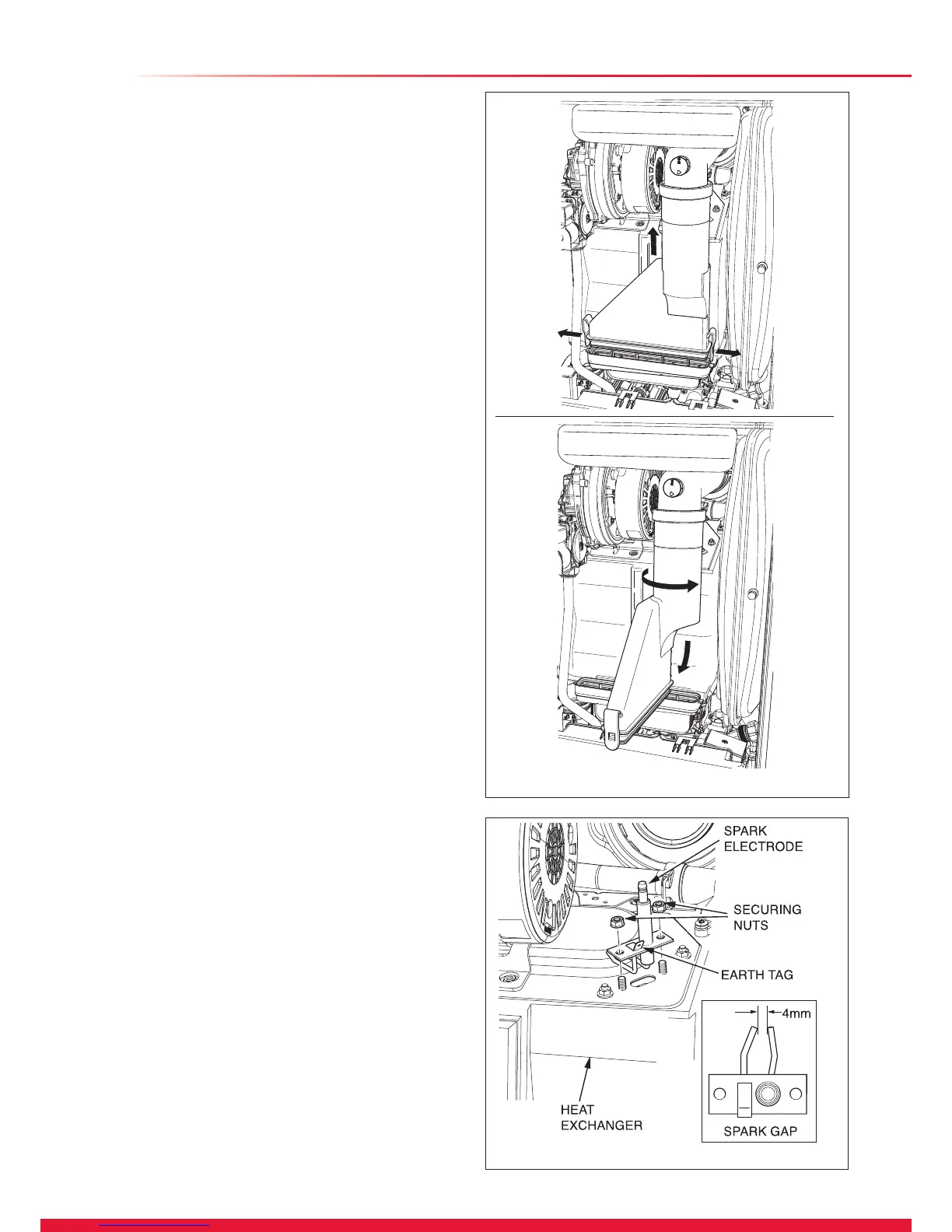
Ease the securing clips away from the sump to release the
retaining catch then push the ue hood up to disengage from
the sump, see diagram 13.5.
To remove, swivel ue hood 90
o
and pull down and out, see
diagram 13.5.
Check seal for wear or damage and replace if necessary.
IMPORTANT: Do not allow xings, nuts, screws, etc. to fall
into the open ue hood sump, use a temporary cover whilst
removing any parts.
Disconnect the spark electrode plug and earth lead. Remove
the two securing screws and withdraw the spark electrode
carefully from the combustion chamber, see diagram 13.6.
Inspect the tips for damage.
Clean away any debris and check the spark gap is 4mm.
Check the electrode gasket for signs of damage and replace
if necessary.
13.3 Burner
NOTE: If the functional checks did not indicate poor
combustion then it is not necessary to service this
component.
Disconnect the gas supply at the gas valve and electrical
connections, see diagram 13.7.
The Silencer (front) is a push t, so there is no need for tools
to remove or t, see diagram 13.8.
Release the igniter unit support bracket, see diagram 13.9.
Remove the fan retaining bracket.
To ease removal of the securing nut from the fan retaining
bracket, a at bladed screwdriver can be used in the position
shown and gently levered down as indicated, see diagram
13.10.
Remove the fan and gas valve assembly.
The silencer (rear) is a push t so no tools are required for its
removal or tting, see diagram 13.9.
Check the spark electrode gap is 4mm. Clean and adjust as
necessary, see diagram 13.6.
It should not be necessary to remove the spark electrode from
the burner during servicing.
Remove the anged nuts and studs that secure the burner,
note that two studs at the rear also hold the fan clamping
bracket, see diagram 13.12.
Clean the burner with a soft brush taking great care not to
damage the surface of the burner. DO NOT use wire or sharp
instruments to clean the mesh of the burner.
NOTE: The burner gasket should be inspected but will not
need replacing unless there are signs of wear or damage.
Follow the tightening sequence when re-tting the burner, see
diagram 13.12.
13.4 Heat Exchanger
NOTE: If the functional checks did not indicate poor
combustion then it is not necessary to service this
component.
Remove loose debris from inside the heat exchanger using a
soft brush and vacuum cleaner.
Carefully ush by spraying water into the heat exchanger, any
remaining debris should pass through the condensate trap
(Ensure the water is kept away from electrical components).
15585
Diagram 13.5
Diagram 13.6
14408
15586

 Loading...


