31
10 Vertical - Flue Length, Preparation and Installation
14849
Diagram 10.23
Flue Installation
IMPORTANT:-
The ue seals are sensitive to mineral oil based lubricants. Do
not grease the seals. If the seals do need to be lubricated
use only water.
During the installation of the ue system, ensure that debris
such as mortar, lings or swarf are cleared from the ue
system before completion.
Long lengths of ues must be secured to the walls or ceilings
they run against. Use at least one xing bracket for every ue
extension that is used.
After cutting inner ue tubes ensure that you de-burr and
chamfer the male tube end to prevent damage.
Inspect the ue pipes before tting and do not install damaged
or dented ue components.
When assembling the ue system, ensure that the inner
seals are not damaged, do not install a ue component with a
damaged seal.
When tting ue elbows ensure that they are tted at the
correct angle to avoid strain, this will ensure that the seal ts
correctly preventing leakage.
Remove the top ue outlet cover complete with resonator and
discard, see diagram 10.4.
Refer to diagram 10.25 and secure the ue adapter in position
on top of the boiler with four screws supplied, making sure
the nib ts into the locating slot in the boiler casing to ensure
correct orientation.
Secure the rst extension pipe to the ue adapter with the
securing collar supplied by positioning the collar centrally over
the joint, then tighten the two screws on the securing collar,
see diagram 10.26.
Fit more extension pipes as required using the collar and
screws supplied with each extension pipe. To t position the
collar centrally over the joint, tighten the two screws on the
securing collar. Using the holes provided in the securing
collar drill and insert the two self tapping srews supplied, see
diagram 10.27.
The rubber ‘O’ rings of each section should be lubricated prior
to assembly.
Project the rise of the ue pipe to roof level and cut a 150mm
hole in the roof.
Flue Terminal Installation
(a) Pitched Roof
Fit the required pitched roof weather collar over the 150mm
hole in the roof. Make good the tiling or slating around the
collar incorporating the ashing of the weather collar. Position
the angle cap over the weather collar in the correct orientation
to attain the correct angle for your roof.
(b) Flat Roof
Fit the aluminium weather collar over the 150mm hole in the
roof ensuring a weather tight seal.
From above carefully place the ue terminal through the
weather collar.
Flue Terminal to Boiler Connection
Should the clearances above the boiler to roof not allow for
extensions, it is permitted to cut the ue terminal ensuring the
relationship of ue and air duct lengths are retained.
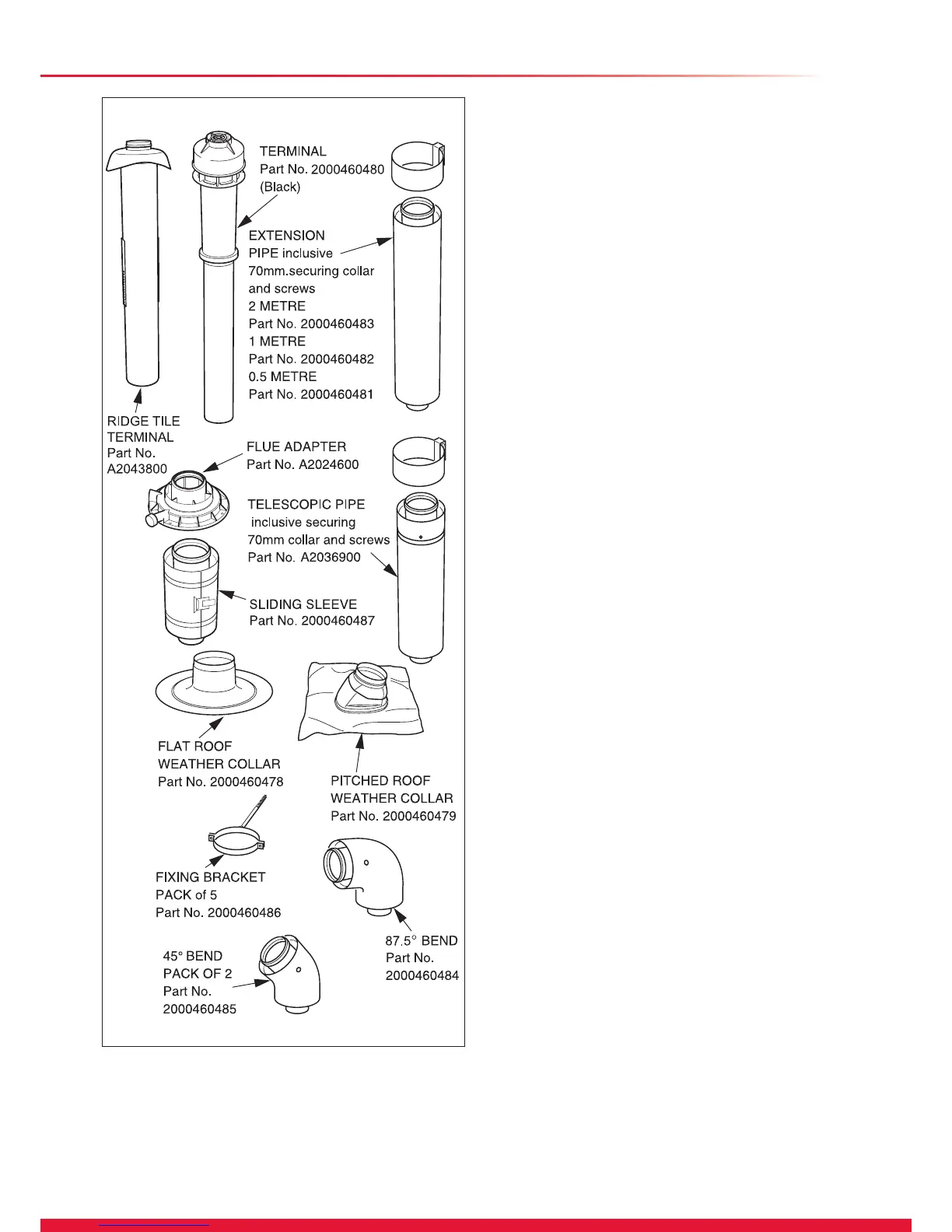
Ridge Tile Terminal
A ridge tile terminal is available - part no. A2043800, see
diagram 10.24.
The installation of a ridge tile will be required.
A suitable ridge tile is manufactured by: -
Aspect East Anglia Limited
The Old Mill
East Harling
NORWICH
NR16 2QW
Website: www.aspectroong.co.uk
Contact: Chris Haythorpe
General Manager - Tile Division
Tel: 01953 717777 Fax: 01953 717164

 Loading...


