53
15 Replacement of Parts
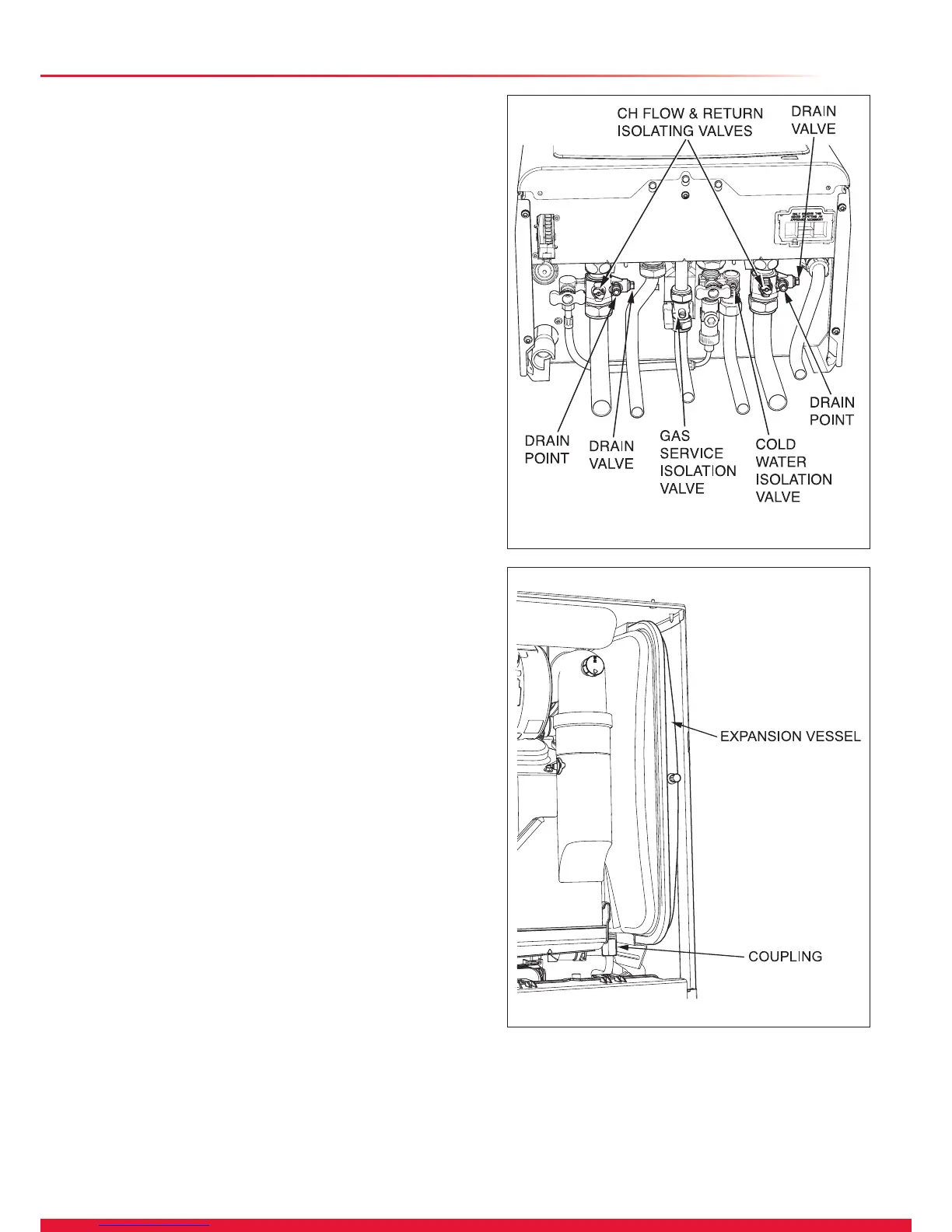
Diagram 15.1
13931
Diagram 15.2
15584
15.1 General
Replacement parts that have associated components that
need replacing on removal, i.e. ‘O’ ring, seals, gasket, etc.,
will be supplied and should be tted.
Replacement of parts must be carried out by a competent
person approved at the time by the Health and Safety
Executive.
Before replacing any parts of the boiler it should be isolated
from the mains electric supply and the gas should be turned
off at the gas service isolation valve on the boiler, see
diagram 15.1.
Unless stated otherwise parts are replaced in the reverse
order to removal.
After replacing any parts always test for gas tightness and if
necessary carry out functional test of the controls.
Boiler Access
For replacement of parts the front casing of the boiler will
need to be removed. To remove undo the two screws on the
underside of the front casing and lift off.
If the appliance site situation has sufcient side clearances
the side panels can be hinged sideways and removed to aid
replacement of parts.
To hinge a side panel undo and remove the four screws
securing each side panel to the boiler, two below and two at
the top.
Draining of Boiler Heating Circuit
Drain down the Heating Circuit of the boiler only, by closing
the heating ow and return isolating valves on the wall
mounting jig. Attach a length of hose to the drain point and
open the drain valve, see diagram 15.1.
After replacing parts, close the drain valve and remove the
hose. Open the heating ow and return isolating valves and
rell, vent and pressurise the heating circuit, refer to section
12.
Check for leaks.
Draining of Boiler Hot Water Circuit
Drain the Domestic Hot Water circuit by closing the cold-water
isolation valve on the wall mounting jig, see diagram 15.1.
Open one or more hot water taps to drain the hot water circuit.
After replacing parts open the cold-water isolation valve and
slowly open a hot water tap to remove air. Close the hot water
tap and check for any leaks.
15.2 Igniter Unit
For access, refer to section 15.1.
Remove ignition lead and electrical connections then remove
igniter unit by removing two securing screws, see diagram
13.9.
15.3 Ignition Lead
For access, refer to section 15.1.
Pull the spark plug style connector off the spark electrode
and the spade connector connected to the igniter unit, see
diagram 13.6.

 Loading...


