39
12 Commissioning
13895
12.3 Filling Domestic Water Circuit
Fully open any valves in the domestic water supply to the
boiler.
Open the domestic water isolation valve, slot in line with the
length of the valve (shown closed in diagram).
Open all hot water taps in turn and close them when water
ows. Check for water soundness of the complete domestic
water system.
The water ow rate is restricted by a restrictor factory tted to
the boiler.
12.4 Re-pressurising System
1. Ensure that the exible hose is connected to the double
check valve by tightening the knurled nut marked ‘E’.
2. Open the two lling taps marked ‘D’ by rotating them
through 90
O
to ll the heating system to a pressure of
1.0bar. Close the two lling taps marked ‘D’.
3. Vent all air from the system - repeat step 2 as neccessary
until the system is full and all the air has been removed.
4. To comply with the water regulations the exible hose must
be disconnected from the double check valve - undo the
knurled nut marked ‘E’ and pull the exible hose from the
double check valve.
12.5 Gas Supply
The gas valve is factory set for natural gas (G20) and should
need no adjustment. Turn on the gas supply at the isolation
valve, see diagram 12.1. Check the supply pressure at the
pressure test point is 20mbar.
Commissioning should only be carried out by a competent
person approved at the time by the Health and Safety
Executive.
12.6 Initial Lighting
NOTE: The combustion for this appliance has been
checked, adjusted and preset at the factory for operation
on natural gas (G20) as dened on the appliance data
label.
Do not adjust the Gas/Air ratio valve.
No measurement of the combustion is necessary, having
checked :
● the appliance has been installed in accordance with the
instructions.
● the integrity of the ue system and ue seals.
● that all internal/external controls are calling for heat.
● the gas service isolation valve, diagram 12.1, is open.
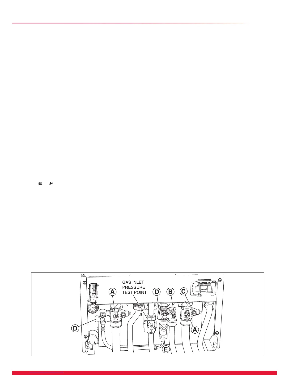
Diagram 12.1
5. Open the two lling taps marked ‘D’ by rotating them
through 90° to ll the heating system to a pressure of
1.0bar. Close the two lling taps.
6. Vent all air from the system - repeat step 5 as neccessary
until the system is full and all the air has been removed.
7. Close the Domestic Cold Water isolation valve marked
‘B’ using a screwdriver or a 3mm allen key (shown closed
in diagram).
8. Close the Central Heating Flow and Return isolation
valves marked ‘A’ using a screwdriver or a 4mm allen key
(shown closed in diagram). If the manometer kit was used,
close drain point marked ‘C’ and remove the manometer.
9. To comply with the water regulations the exible hose
must be disconnected from the double check valve - undo
the knurled nut marked ‘E’ and pull the exible hose from
the double check valve.
12.2 Filling the System and Boiler
1. Ensure that the exible hose is connected to the double
check valve by tightening the knurled nut marked ‘E’.
2. Open the Central Heating Flow and Return isolation valves
marked ‘B’ using a screwdriver or a 4mm allen key - slot
in line with the axis of the isolation valve (shown closed in
diagram).
3. Open the Domestic Cold Water cock marked ‘B’ using a
screwdriver or a 3mm allen key - slot in line with the axis
of the isolation valve (shown closed in diagram).
4. Switch on the appliance, refer to diagram 12.2.
Set the Central Heating temperature and the Domestic Hot
Water temperature to OFF by pressing the MODE button
on the User Interface until it shows the appropriate symbol
and then pressing the - (minus) SELECTOR
button.
The display will now permanently show system pressure.
5. Open the two lling taps marked ‘D’ by rotating them
through 90
O
to ll the heating system to a pressure of
1.0bar. Close the two lling taps marked ‘D’.
6. Vent all air from the system - repeat step 5 as neccessary
until the system is full and all the air has been removed.
7. After lling is complete set the Central Heating
temperature and the Domestic Hot Water temperature
to the desired level using the MODE and + (plus)
SELECTOR buttons as described above.
8. To comply with the water regulations the exible hose
must be disconnected from the double check valve - undo
the knurled nut marked ‘E’ and pull the exible hose from
the double check valve.

 Loading...


