41
12 Commissioning
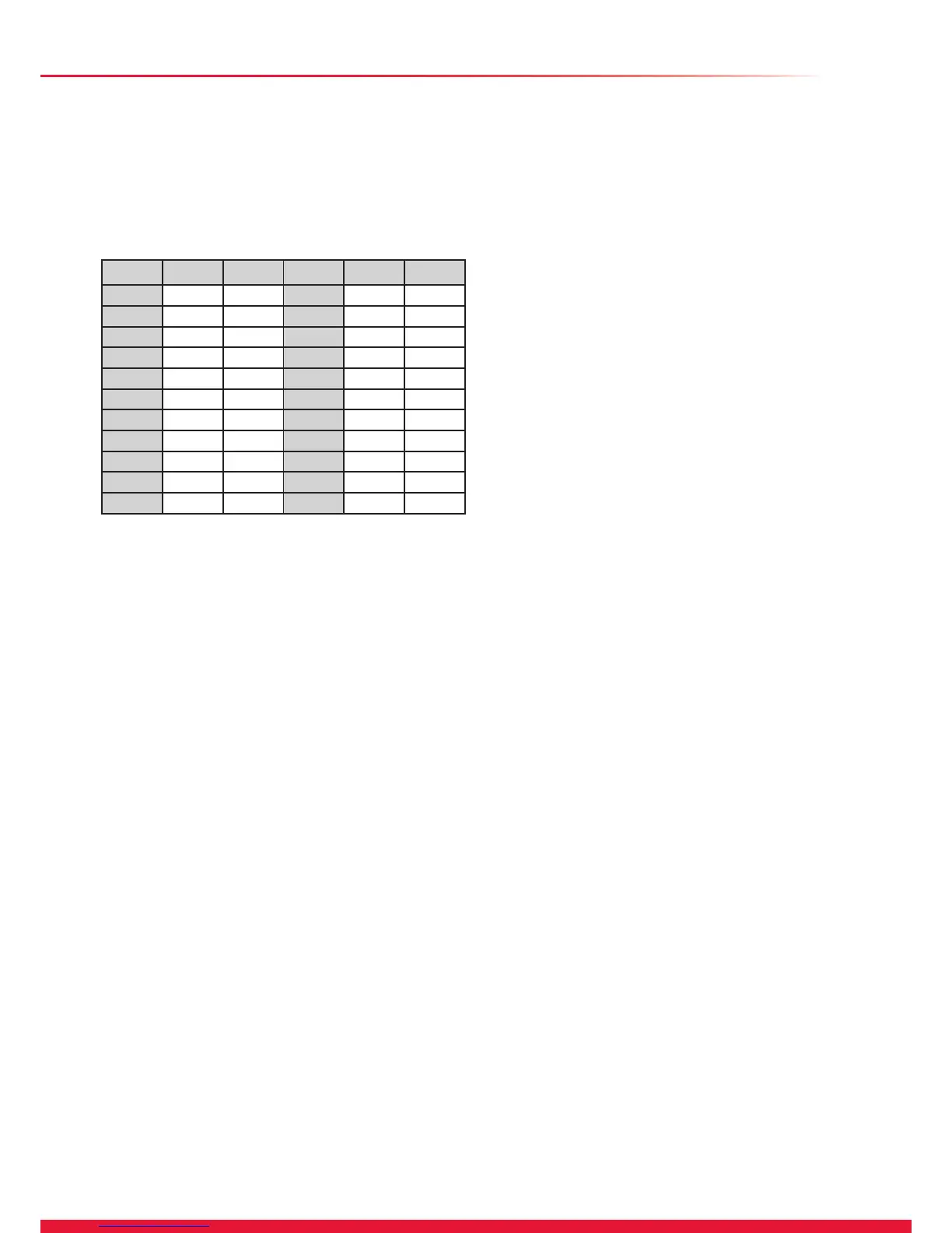
Gas Rate
Make sure that ALL other gas burning appliances and pilot
lights are off.
Check the gas rate using the gas meter test dial and stop
watch, at least 10 minutes after the burner has lit.
The approximate maximum gas rates are:
The appliance pump has two speeds and can be adjusted to
suit the requirements of the system.
The appliance has an inbuilt automatic adjustable bypass
valve. The pressure can be adjusted between approx 1.5
and 3.5mH
2O but is factory pre-set to approx 2.5mH2O. The
pressure changes by approx 0.1mH
2O for each full turn of the
bypass screw, see diagram 5.2. Turning clockwise increases
the pressure and turning anti-clockwise decreases the
pressure.
Allow the system to reach maximum temperature then switch
off the boiler by isolating from the electrical supply.
Drain the entire system rapidly whilst hot, using the drain taps
at all the low points of the system. Fill and vent the system as
described previously in section 12.2.
Lock or remove the handle from control valve, if tted.
Adjust the boiler temperature controls and any system
controls to their required settings.
12.10 Completion
Ensure that the magnetic lighting instruction label is placed on
the surface of the boiler casing.
GB: In addition it is necessary to complete the “Benchmark”
logbook.
IE: it is necessary to complete a “Declaration of Conformity” to
indicate compliance to I.S.813. An example of this is given in
the current edition of I.S.813.
12.11 Instruct the User
● Demonstrate, then instruct the User about the lighting
procedure and heating system controls operation.
● Advise that to ensure the continued efcient and safe
operation of the boiler it is recommended that it is checked
and serviced at regular intervals. The frequency of servicing
will depend upon the installation conditions and usage, but in
general, once a year should be enough.
● Draw attention, if applicable, to the current issue of the Gas
Safety (Installation and Use) Regulations, Section 35, which
imposes a duty of care on all persons who let out any property
containing a gas appliance in the UK.
● The user shall not interfere with or adjust sealed
components.
● It is the Law that any servicing is carried out by a
competent person approved at the time by the Health and
Safety Executive.
● Advise the user that, like all condensing boilers this
appliance will produce a plume of condensation from the ue
terminal in cool weather. This is due to the high efciency and
hence low ue gas temperature of the boiler.
● Advise the user of the precautions necessary to prevent
damage to the system, boiler and the building, in the event of
the heating system being out of use during frost or freezing
conditions.
● Advise the user that the permanent mains electrical supply
SHOULD NOT be switched off, as the built in frost protection
and pump saver program will not operate.
● Advise the User if the mains electricity and gas are to be
turned off for any long periods during severe weather, it is
recommended that the whole system, including the boiler,
should be drained to avoid the risk of freezing.
NOTE: Sealed System: Contact your installation/servicing
company as draining, relling and pressurising MUST be
carried out by a competent person approved at the time by
the Health and Safety Executive.
● Leave these instructions and the ‘Benchmark’ Installation,
Commissioning and Service Record with the user.
kW m3/hr ft3/hr kW m3/hr ft3/hr
20 2.1 74.2
30 3.2 113 19 2.0 70.6
29 3.1 109.5 18 1.9 67.1
28 3.0 106 17 1.8 63.6
27 2.9 102.4 16 1.7 60.0
26 2.8 98.9 15 1.6 56.5
25 2.6 91.8 14 1.5 53.0
24 2.5 88.3 13 1.4 49.5
23 2.4 84.8 12 1.3 45.9
22 2.3 81.2 11 1.2 42.4
21 2.2 77.7 10 1.1 38.9
12.8 Central Heating Range Rating
The boilers are fully modulating for central heating, therefore
it is not necessary to range rate them, however, if desired, you
can adjust the CH output in 1kW increments between:
24cx : 10 - 18kW
30cx : 10 - 24kW
35cx : 10 - 30kW
as follows:
a) Press and hold the ‘MODE’ and “+” button for 5
seconds. The display will change to ashing ‘0’.
b) Use the ‘+’ or ‘-’ button to scroll to 96.
c) Press ‘MODE’ and hold 5 seconds to conrm.
d) The display now shows a ashing ‘d. 0’.
e) The part load setting is displayed in kW.
Press ‘MODE’ the max rate will be indicated, to
change the value to the desired setting, use the ‘+’
or ‘-’ button.
f) Press ‘MODE’ for 5 sec to conrm the new setting
has been saved.
g) Press and hold ‘MODE’ and “+” to exit.
Please refer to the above table to check the gas rates.
12.9 Heating System
Ensure that the external controls and programmer are calling
for heat.
Fully open all radiator valves, ow control valve, if tted, see
diagram 5.1.
Press the “MODE” button to change to the CH.
Balance the radiators as required and if tted adjust valve to
give the required system differential. Turn off all radiators that
can be shut off by the user and check to see if less than the
maximum differential allowed of 20
o
C can be achieved across
ow and return.
NOTE: Should the system require that the appliance has
to be adjusted, the front casing will need to be removed as
described in the servicing section 13 and the control box
lowered into its service position.
24cx : 1.9m3/h (68ft/3/h)
30cx : 2.6m3/h (92ft/3/h)
35cx : 3.3m3/h (115ft/3/h)

 Loading...


