19
Diagram 7.4
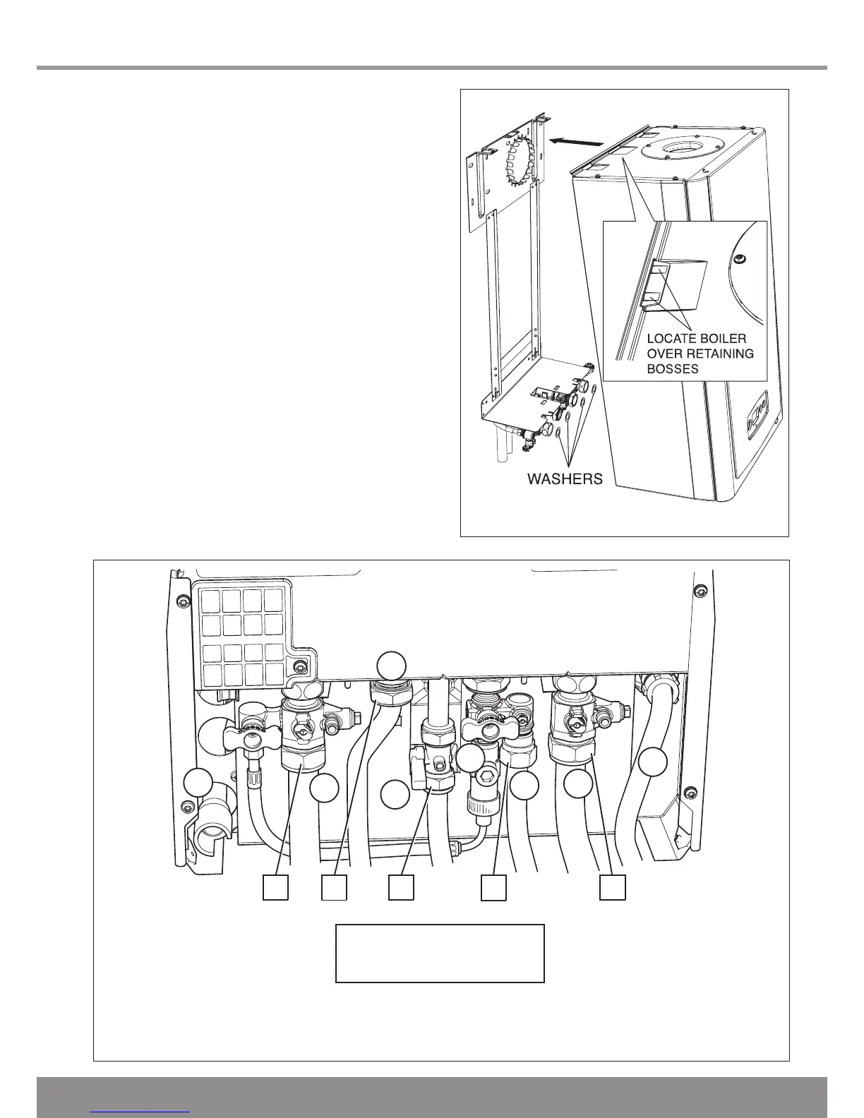
A - Central Heating Isolation Valve
B - Domestic Hot Water
C - Gas Service Cock
D - Domestic Cold Water
E - Washers (not shown)
F - Condensate Connection
G - Double check inlet valve
H - Safety Discharge Valve
7 Gas / Water & Appliance Connection
Diagram 7.3
12777
7.2 Appliance Connection
IMPORTANT: With regards to the Manual Handling
Operations, 1992 Regulations, the following lift operation
exceeds the recommended weight for a one man lift, refer to
section 16 Manual Handling.
Rear Flue only
This must be fitted before hanging the boiler, refer to Section 9.
NOTE: The appliance and jig (pre-filled) may contain a small
amount of water, place a water container beneath the boiler
connections.
Make sure the isolation valves are closed before disconnecting
the blanking plugs and discarding the jig plate.
Position the sealing washers supplied in the Loose Items pack,
as shown in diagram 6.1.
Lifting the boiler into position, lean the top of the boiler slightly
to the wall and position just above the hanging bracket. Lower
the boiler slowly push back and engage onto the hanging
bracket making sure the boiler is located over the retaining
bosses, see diagram 7.3.
Remove the protective caps.
Engage the fixing jig connections, ensuring that the previously
positioned washers have not been disturbed.
Make good the final connections.
Numbers 1 - 5
show the sequence to be used
when tightening to copper tails.
12955

 Loading...


