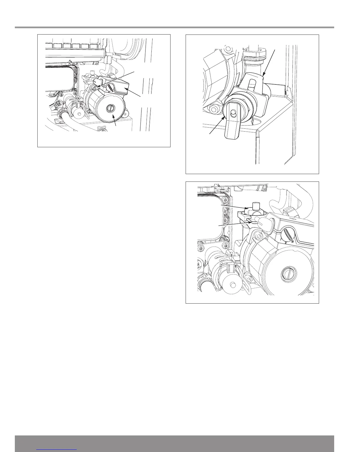
Diagram 14.17
12666
14.20 Pump (head only)
For access, refer to section 14.1.
Refer to section 14.2 and drain the boiler heating circuit.
Refer to diagram 14.17.
Remove the four cap head screws.
Carefully remove the pump head together with cable. Do not
strain cable.
Support the pump head, unscrew cable cover at the side of
pump head and remove.
Disconnect wiring from pump head.
Reconnect wiring to new pump head and fit cover.
Fit the new pump head with ‘O’ ring.
Refill, vent and pressurise the boiler and check for leaks.
14.21 Safety Discharge Valve
For access, refer to section 14.1.
Refer to section 14.2 and drain the boiler heating circuit.
Refer to diagram 14.18.
Undo the safety discharge valve union and remove from the
pipework.
Remove the retaining clip and withdraw the safety discharge
valve.
Fit new ‘O’ ring.
Refill, vent and pressurise the boiler and check for leaks.
14.22 Automatic Air Vent
For access, refer to section 14.1.
Refer to section 14.2 and drain the boiler heating circuit.
Refer to diagram 14.19.
Remove the retaining clip to release the automatic air vent.
Fit the new automatic air vent and ‘O’ ring ensuring the vent
cap is left loose.
Refill, vent and pressurise the boiler and check for leaks.

 Loading...


