14 Replacement of Parts
Diagram 14.21
12668
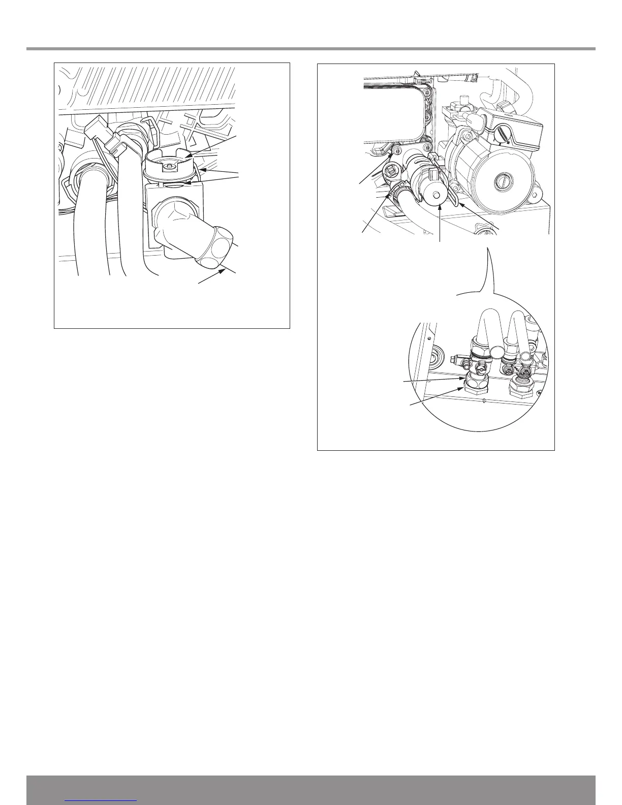
Diagram 14.20
14.23 Flow Sensor
For access, refer to section 14.1.
Refer to section 14.3 and drain the boiler hot water circuit.
Refer to diagram 14.20.
Undo the brass securing nut on the domestic cold water
return pipe.
Remove the securing clip between the hydroblock and the
flow sensor.
Remove the electrical connection to the flow sensor.
Remove the securing clip holding the brass elbow to the flow
sensor.
Partially withdraw the flow sensor to allow removal of the elec
-
trical connection before full removal of the sensor.
Remove flow sensor.
Fit new ‘O’ rings.
After replacing the flow sensor, open the cold-water isolation
valve and slowly open a hot water tap to remove air.
Close the hot water tap and check for any leaks.
14.24 Three Way Valve
For access, refer to section 14.1.
Refer to section 14.2 and drain the boiler heating circuit.
Refer to section 14.3 and drain the boiler hot water circuit.
Refer to diagram 14.21.
Undo the nut retaining the heating return isolation valve to the
fixing jig. Be careful not to lose the sealing washer.
Undo the securing nut on the underside of the fixing jig and
pull the pipe away from the three-way valve assembly.
Fully remove the three securing screws and pull the three-way
valve assembly towards the left to disengage from the hydrob-
lock. (Ensure that the original o-ring has not been retained in
the hydroblock.)
Fit the new three-way valve assembly.
Reassemble, refill, vent and pressurise the boiler and check
for leaks.

 Loading...


