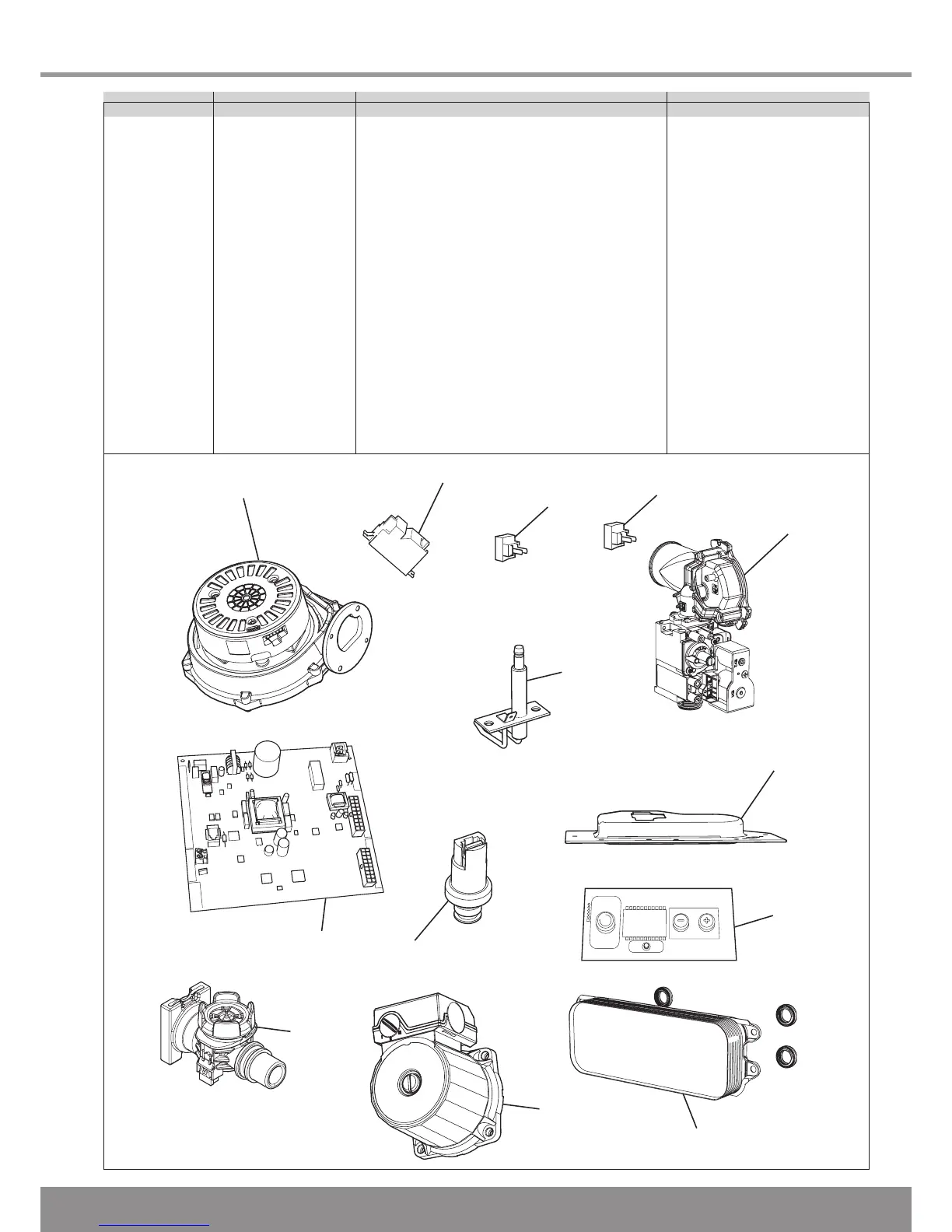
EasyManuals Logo

Glow-worm Flexicom 24cx Installation And Servicing

Glow-worm Flexicom 24cx
60 pages
To Next Page IconTo Next Page
To Previous Page IconTo Previous Page
Page #57 background imageLoading...
Page #57 background image
57
1
2
3
5
6
7
8
12
4
9
11
10
13
15 Spare Parts
Diagram 15.1
13031
Key No. Part No. Description GC No
1 0020020734 Fan XXXXXX
2 0020020763 Igniter unit XXXXXX
3 0020020781 Heating flow & return thermistor (2) XXXXXX
4 0020014160 DHW thermistor XXXXXX
5 0020020735 Gas valve XXXXXX
6 0020020731 Electrode XXXXXX
7 0020020728 Burner XXXXXX
8 XXXXXXX User interface XXXXXX
9 0020014402 Plate to plate heat exchanger 24/30cx XXXXXX
10 0020014180 Pump (head only) XXXXXX
11 0020014174 Flow sensor XXXXXX
12 XXXXXXX Main PCB XXXXXX
13 0020014190 Water pressure sensor XXXXXX

Other manuals for Glow-worm Flexicom 24cx

Questions and Answers:

Question and Answer IconNeed help?

Do you have a question about the Glow-worm Flexicom 24cx and is the answer not in the manual?

Glow-worm Flexicom 24cx Specifications

General IconGeneral
Boiler TypeCombi
Fuel TypeNatural Gas
Central Heating Output24 kW
DHW Flow Rate9.8 l/min
ErP Efficiency RatingA
Central Heating Flow Temperature Range30 - 80°C
Weight31 kg
Warranty2 years

Related product manuals