37
11 Commissioning
11.5 Initial Lighting
The lighting procedure of the boiler is fully automated.
Check that all external controls are calling for heat.
The digital display will show water temperature in central
heating demand. The appliance will enter a self checking
routine then the fan should start and the ignition will
commence.
If the burner fails to light the fan will stop. Initially this may be
due to air in the gas supply line. The boiler will automatically
have five attempts at ignition.
If the burner fails to ignite the display will show F1.
Depress the ‘reset’ button on the fascia to clear the display
and repeat the ignition sequence.
Once the system has been purged of air set the hot water
to the desired temperature by using the MODE and + (plus)
SELECTOR buttons.
Open a hot water tap, the diverter valve motor will move to
hot water supply and the display will read domestic hot water
temperature.
Check that hot water is available and then close the hot water
tap.
Set the Central heating water temperature to the desired
temperature by using the MODE and + (plus) SELECTOR
buttons.
The appliance will then continue to fire in central heating until
the user controls are satisfied or there is another demand
made for hot water.
NOTE: After ignition in central heating demand the boiler will
ramp slowly to full rate rather than going immediately to full
rate. This is an adaptive feature to cope with small system
requirements.
11.6 Testing
Should any doubt exist about the gas rate, check it using
the gas meter test dial and stop watch at least 10 minutes
after the burner has lit, making sure that all other gas burning
appliances and pilot lights are off.
It should be noted that this appliance will modulate the heat
input according to demand. This may affect the gas rates
measured if the appliance reaches its operating temperature
during the measurement.
The approximate gas rates:
24cx : 1.9m3/h (68ft3/h)
30cx : 2.6m3/h (92ft3/h)
The gas valve is factory set for natural gas (G20) and should
need no adjustment. It should be checked that the supply
pressure is 20mbar when the boiler is firing at full rate. This
can be achieved by turning on several hot water taps and
checking the inlet pressure at the inlet pressure test point
on the gas inlet cock on the fixing jig. Turn taps off and
disconnect pressure gauge.
In the unlikely event that the gas valve needs adjusting,
refer to section 12.6. Re-setting of the gas valve requires
a combustion analyser and any adjustment should only be
carried out by a competent person.
Note that the burner pressure cannot be measured at the gas
valve as it is altered by the suction of the fan and modulated
according to demand.
11.7 Testing - Heating System
Check that all external controls are calling for heat. The boiler
will fire automatically. Fully open all radiator valves, flow
control valve, if fitted, see diagram 4.1.
Balance the radiators as required and if fitted adjust valve to
give the required system differential. Turn off all radiators that
can be shut off by the user and check to see if less than the
maximum differential allowed of 20
o
C can be achieved across
flow and return.
The pump has two speeds and can be adjusted depending on
the requirements of the central heating system, see diagram
4.2.
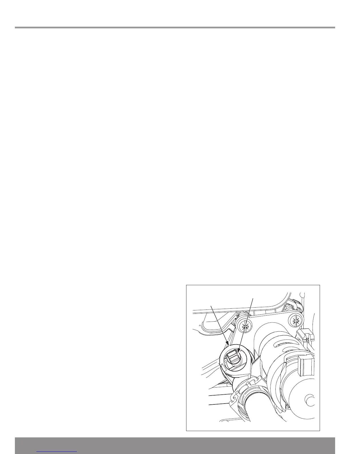
The appliances have an inbuilt automatic adjustable bypass
valve, see diagram 11.2. The pressure can be adjusted
between approx 1.5 and 3.5mH2O.
The bypass is factory pre-set to approx 2.5mH2O. The
pressure changes by approx 0.1mH2O for each full turn
of the bypass screw, see diagram 11.2. Turning clockwise
increases the pressure and turning anti-clockwise decreases
the pressure.
Allow the system to reach maximum temperature then switch
off the boiler by isolating from the electrical supply.
Drain the entire system rapidly whilst hot, using the drain tap
at the lowest part of the system. Fill and vent the system as
described previously in section 11.4.
Lock or remove the handle from control valve, if fitted.
11.8 Completion
Adjust the boiler temperature control and any system controls
to their required settings. In addition it is necessary to
complete the “Benchmark” logbook.
For IE, it is necessary to complete a “Declaration of
Conformity” to indicate compliance to I.S.813. An example of
this is given in the current edition of I.S.813.
Testing Flue Gases: If any doubt exists that the flue
products are not exhausting correctly, investigate by use of a
gas analyser (FGA).

 Loading...


