Diagram 14.22
12812
14.25 Heat Exchanger
For access, refer to section 14.1.
Remove silencer front, flue hood, gas valve / burner assem
-
bly, spark electrode lead, burner and condense trap.
Refer to section 14.2 and drain the boiler heating circuit.
Refer to section 14.3 and drain the boiler hot water circuit.
Remove the retaining clip from the flexible hose connection
into the brass elbow on the lower left hand side of the heat
exchanger. Detach the flexible hose.
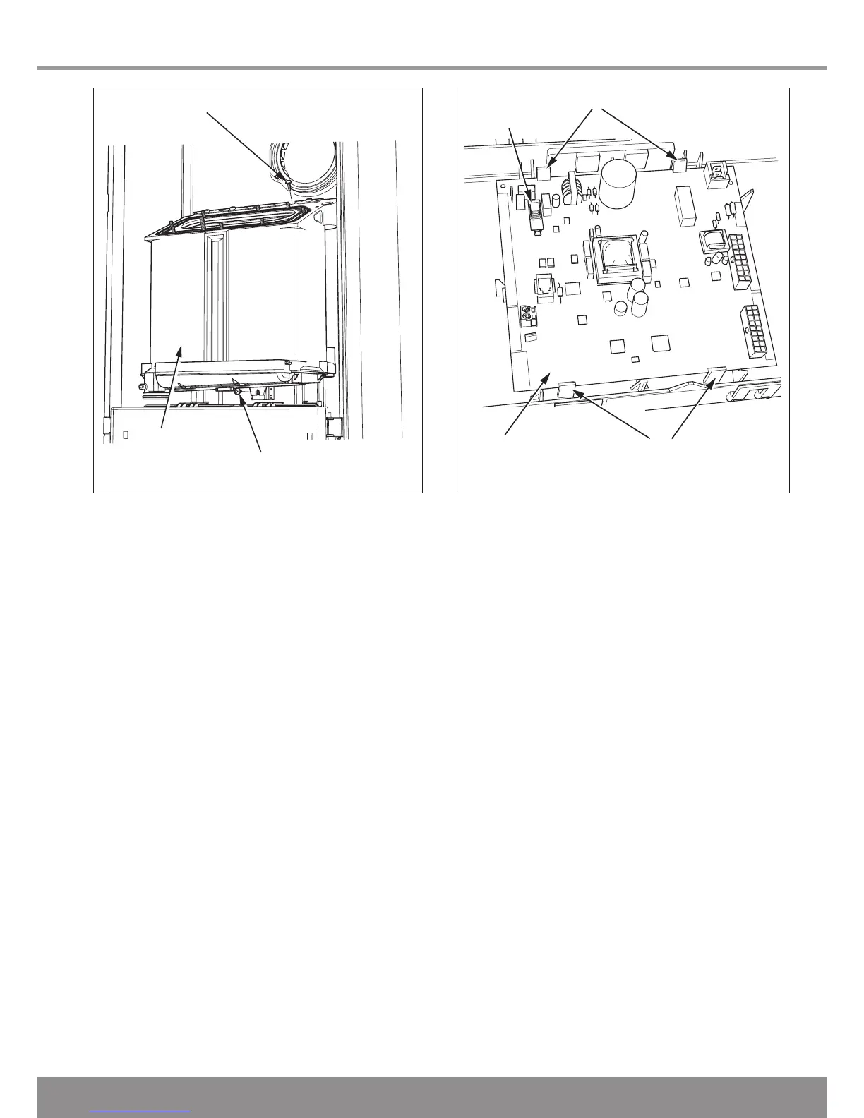
Remove screws securing the heat exchanger, one on top and
one underneath the heat exchanger, see diagram 14.22.
Undo the knurled nut at the right hand side of the hydroblock.
Remove the retaining clip from the flanged elbow at the right
hand bottom of the heat exchanger.
Remove the flow pipe.
Lift up heat exchanger slightly to disengage it from its hanging
bracket.
Remove the heat exchanger by pulling forward and tilting
backwards to ease removal complete with sump, return pipe
and flanged elbows.
14.26 Access to User interface and Main
PCB
For access, refer to section 14.1.
Hinge down the control box and unclip the rear cover to gain
access.
Remove electrical connections from main PCB noting their
positions for replacement.
Unclip main PCB and remove, see diagram 14.23.
Unclip user interface and remove.
For replacement, see diagram 14.24 and ensure that the user
interface connection cable is refitted.
NOTE: When re-fitting any of the control boards make sure
you support the control box to avoid straining hinges as you
push down and clip back into place.
Diagram 14.23
13003

 Loading...


